Plan Shapes
Details
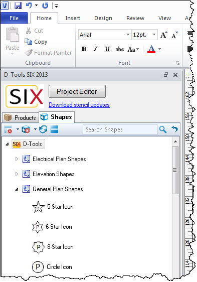
General Plan Shapes
Plan Shapes are generally simple shapes intended to show placement of equipment from an overhead view, e.g. on top of a floor plan. They are located in the General Plan Shapes Stencil:
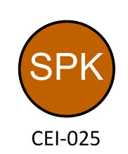
The text that is displayed in the icon shapes are based on the abbreviation of the Category of the Product. The text on the bottom is the unique Component ID of the Product. An example Plan Shape is shown below:
Electrical Plan Shapes
The Electrical Plan Shapes stencil contains all of the shapes that could be used in documenting high voltage electrical and lighting projects. It contains a selection of lighting fixtures, electrical outlets and electrical switch shapes. Most of the shapes have mount type and device type options via the Shape Data UI or right-click. More info at these links: http://www.d-toolsblog.com/d-tools-n...ng-plan-icons/ and http://www.d-toolsblog.com/newslette...an-icon-shape/ and http://www.d-toolsblog.com/d-tools-n...t-switch-icon/
 .
.
Security and Safety Plan Shapes
The Security and Safety Plan Shapes stencil has most of the legacy shapes needed for documenting these types of installations. All of these shapes have been updated with the same right-click and shape data UI improvements as the other plan shapes.

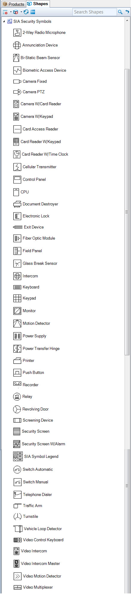
SIA Security Symbols
We recreated the SIA security symbols and added automation for mount type and device options per the SIA/IAPSC AG-01-1995.12 (2000.03) document. More information here: http://www.d-toolsblog.com/?p=10303
Shape Data Window
All user adjustments are accessed through the Shape Data window.
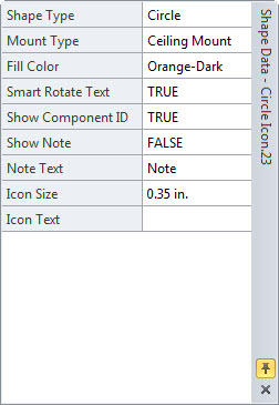
Shape Type: There are 12 distinctly different shape types within this shape that can be assigned to a specific category in a project by the designer by using the Shape Type selection in the Shape Data UI. The Plan Icon shape will automatically configure itself based on the user shape choices.

Mount Type: There are three different choices for Mount Type that will automatically render based on the user choices.
- Ceiling Mount is the default and is just the plain icon shape of choice.
- Floor Mount is the icon shape of choice with a box surrounding the shape.
- Wall Mount is the icon shape of choice with a "T" shape handle off of the left side of the shape.

Fill Color: We implemented a new color schema for the plan shapes based on the "Rothian" color scale. The default is white but can easily be changed by using the right-click>>Color menu or using the Shape Data window. If you want to change colors across multiple shapes at once multi-select the shapes you want to change and use the Shape Data UI.
Speaking of colors we also implemented a smart text functionality that evaluates the background color for brightness and will automatically change the internal text to black or white depending on the brightness level of the background color. If you notice the picture below the white, orange, and green shapes have black text while the blue is white.

Show Component ID: True or False, default = TRUE. This will turn the Component ID field on or off. In addition you can use the yellow control handle to move the component ID around the shape as needed. This is useful when you rotate the shape.

Smart Rotate Text: True or False, default = TRUE. What smart rotate does is use the Visio "Gravity" function so the text is always legible no matter which way the shape was rotated. Some users wanted the ability to turn that on and off so we gave it to them as a right-click and a Shape Data option.

Show Note: If set to True you can add text to the Note field and it will show up in the note call out. You can use the yellow control handle to move this text around. Default is set to False.
Note: Any text you add here will end up on the note tag of the plan icon shape.
Icon Size: This is a relative to the scale of the drawing, .35 in is the default. If you want it to be larger than enter a decimal number larger than .35. Do the opposite for smaller.
Icon Text: Free form text field. This field will normally display the Category ID. The Category ID is a preset field that is usually a 3 or 4 letter abbreviation of the specific product category. For example the Speakers category could be abbreviated SPK during setup. If this was the case then the Category ID (CID) on all speaker icons would automatically have SPK in the center. However if you want this shape to display something else in this area all you have to do is type in the text you want into the Icon Text field and it will show up in the shape.
Each plan icon shape also has a little yellow control handle that you can use to move the text around when the shape is selected The right-click/Shape Data options are pretty self-explanatory.
Pre-assigned Categories
We pre-assigned categories and subcategories on the General Plan Shapes according to the table below using our new for SIX 2013 Category Assignment process. These assignments can be easily modified.

Site Map for Projects
- Projects
- Project Explorer
- Project Editor
- Visio Interface
- How-To: Creating a Visio File
- How-To: Adding your Company Logo
- How-To: Creating a Line Drawing
- How-To: Creating a Plan Drawing
- How-To: Creating a Schematic Drawing
- How-To: Creating an Elevation Drawing
- How-To: Creating Custom Templates
- Insert Drawing Pages
- Paste Special
- Product Tree
- Visio Shapes for SIX
- Line Shapes
- Elevation Shapes
- Plan Shapes <– You are here
- Schematic Shapes
- Wire Shapes
- Annotation Shapes
- Assign Categories to Shapes
- Assign Product and Category
- Assign Shapes to Categories
- Change Shape
- Generate Side View
- Import/Export Stencils
- Insert Alternate Shape
- Link to Product (Visio)
- Location and System Shapes
- Lock Stencil
- Selection Settings for Shapes
- Shape Display Settings
- AutoCAD Interface
- Locations
- Sample Projects
- © Copyright 2024 D-Tools