AutoCAD to Visio
Table of contents
Round Tripping: AutoCAD to Visio…then back to AutoCAD
Often the most difficult part of working with an AutoCAD Drawing is getting the AutoCAD file from the architect. The situation may arise when an architect or builder asks that you provide installation drawings integrated with an existing AutoCAD based architectural drawing package. You could print out a 24” x 36” plot, but ideally you would like to provide an electronic file.
This method was designed by Adam Stone, President of D-Tools, Inc. to assist you with this task.
![]() Some of the procedures in this section are repeated elsewhere in our documentation because there are additional specific criteria needed for “round tripping” that are not necessary when not “round tripping”.
Some of the procedures in this section are repeated elsewhere in our documentation because there are additional specific criteria needed for “round tripping” that are not necessary when not “round tripping”.
Basic Facts About Visio and AutoCAD
Before we jump into the process I should go over some AutoCAD terms and how they relate to Visio. The first thing we need to know about AutoCAD is that there are two ways to view a drawing: Paper Space and Model Space. Basically all drawings are done in Model Space and all printing/plotting is done in Paper space. Drawings in Model space are created in the real world scale: 1: 1. Drawings in Paper Space are represented as a scaled version of Model Space so they can fit on paper, typically ¼” = 1’..
The important thing to remember is that Visio imports and exports AutoCAD files in Model Space but uses Paper Space (scale) to work with shapes and objects. Visio does not have a Model Space equivalent; everything is done in Paper Space. When importing AutoCAD files into Visio, it is important to always match the Visio and AutoCAD page scale. If the drawing is saved properly, it will export in Model Space at a 1:1 scale.
Prepare the AutoCAD File for Insertion (requires AutoCAD)
You will need a current version of AutoCAD and some basic knowledge of AutoCAD or AutoCAD Lt to complete this process. If you don’t have AutoCAD, see if you can get the person who gave you the floor plan to follow these instructions. This process assumes the user is working on an Architectural file.
Open original file in AutoCAD in Model Space. The following commands will clean up the drawing and set the reference point.
1) Run the Command: zoom extents
2) Verify that there is only one “view” in the Drawing. Many AutoCAD Drawings have multiple “views” as shown below:
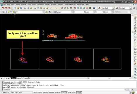
Follow these steps to create a new separate drawing file for each view:
a) Run the command wblock. The Write Block form will open:
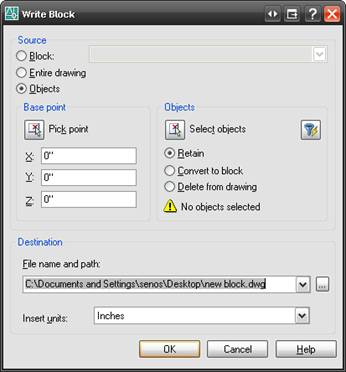
b) Click the [Select objects] button ![]() .
.
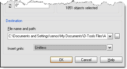
c) Select the objects and then click [Enter] on the keyboard. You will be returned to the Write Block form. Choose a file name and path, and change the Insert units to “Unitless”.
d) Now open the new file you just created in AutoCAD and start over with the Preparing an AutoCAD file for insertion into Visio” process.
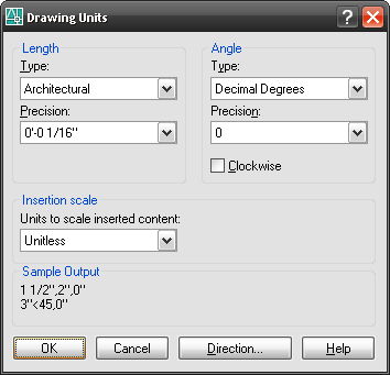
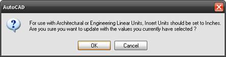
3) Run the Command: units. Verify that the “Type” is set to Architectural and the “Units to scale inserted content” is set to Unitless.
![]() You may see the following prompt, click [OK].
You may see the following prompt, click [OK].
4) Run the Command: zoom Type e for “extents”. Zoom extents will fill the page with the entire drawing.
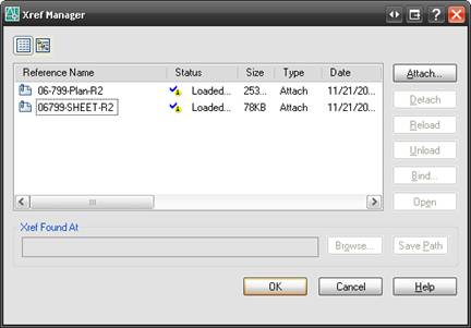
5) Run the Command: xref. The Xref Manager dialog will open.
![]() An xref is an external reference to other CAD files. It is up to the Architect or the person putting together the file to determine which files are needed to be added or deleted from the drawing.
An xref is an external reference to other CAD files. It is up to the Architect or the person putting together the file to determine which files are needed to be added or deleted from the drawing.
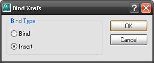
6) If there are xrefs, select all files then click the [Bind] button. The Bind Xrefs dialog will open.
7) Select the Insert option and then click [OK]. Click [OK] to close the Xref Manager. This will bind any externally referenced files to this file.
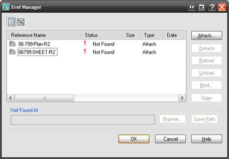
![]() If the xref Status is “Not Found” or “Unloaded”, then select all files, click the [Detach] button and then click [OK].
If the xref Status is “Not Found” or “Unloaded”, then select all files, click the [Detach] button and then click [OK].
8) Run the Command: purge The Purge form will open:
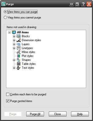
9) Purge removes unused entities from the drawings. Check “Purge nested items” and uncheck “Confirm each item to be purged”.
10)Click [Purge All] until all items are purged (you may have to do this more than once) and then click [Close] to exit the form.
11)Run the Command: audit Type y to fix any errors
12)Run the Command: Base Then type 0,0,0. This sets the insertion base point to 0,0,0.
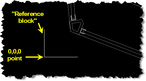
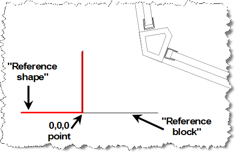
13)Run the Command: line 0,0,0. This will find the origin point of the CAD drawing. The pivot point of the line is the “origin” or “zero point” of the drawing. This is very important if you want the Visio shapes to match the floor plan on export.
14)Draw the line along the x axis to the right of the ‘zero point’ and then hit the [Esc].
15)10. Run the Command: line 0,0,0
16)Draw another line at the pivot point along the y-axis to form a 90 degree angle. The two lines will form an “L”. The corner of the angle is the “0,0,0 point” of the AutoCAD drawing. This “L” will be called the “reference block” When done, hit the Esc key.
![]() You want the base point to be close to the drawing. Sometimes the base point will be set off of the page. This is usually an architect’s mistake or the drawing was based off of a civil drawing. To set a new arbitrary point to use as a reference follow these commands:
You want the base point to be close to the drawing. Sometimes the base point will be set off of the page. This is usually an architect’s mistake or the drawing was based off of a civil drawing. To set a new arbitrary point to use as a reference follow these commands:
e) Run the Command: ucs Type n for new
f) Pick the arbitrary point somewhere in the lower left beyond the boundary of the drawing
g) Run the Command: base Set point to 0,0,0
17)Run the Command: zoom extents
18)Select File->Save as… and save the drawing in AutoCAD 2000/LT2000 Drawing format.
At this stage the file is ready to be exported at its cleanest and most Visio compatible state.
Insert AutoCAD File into Visio as a Background
19)Create a new SI 5 Visio project or open an existing SI 5 Visio project. Make sure you are on a Plan Page Type in the Visio Project:
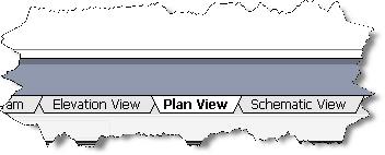
20)Create a background page in Visio. Right-click on the Plan View tab and select Insert Page. The Page Setup form will open.
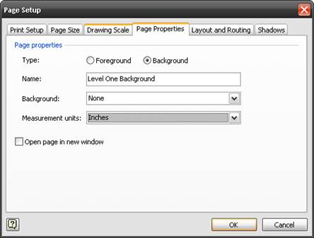
21)From the menu bar select File->Page Setup… The Page Setup form will open.
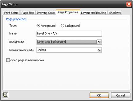
22)Click the Page Properties tab and verify that Measurement Units is set to “Inches”, not “Feet and Inches”. Name the page something appropriate and select the Background radio button for “Type”.
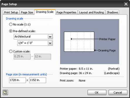
23)Click the Drawing Scale tab and verify that the Pre-defined scale: is set to Architectural ¼” = 1’0”. This is a good scale to start with. Click [OK].
24)You just created a background page in Visio. Insert the AutoCAD file on this page, then “link” the actual pages you will be dropping Visio shapes on to this background page. This method of creating a background page is convenient when you are using the same AutoCAD floor plan on multiple drawing pages, i.e. you want to do a separate page for lighting and a separate page for audio.
25)While the background page is selected, select Insert->CAD Drawing from the menu bar in Visio.
26)Browse to the AutoCAD file and click [Open]. The Insert AutoCAD Drawing dialog box will open.
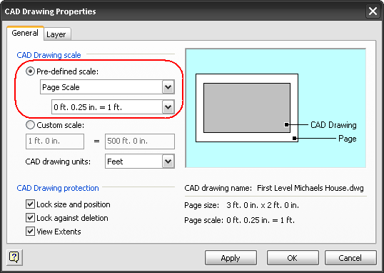
27)The Custom Scale: radio button is selected by default. You must change this to Pre-defined scale: Page Scale. Click [OK]. The CAD drawing will be inserted into the Visio page.
![]() If the AutoCAD drawing is too large for the page size then start the insert over but with a smaller scale from the File->Page Setup->Drawing Scale form (step 23).
If the AutoCAD drawing is too large for the page size then start the insert over but with a smaller scale from the File->Page Setup->Drawing Scale form (step 23).
If the AutoCAD drawing is too small for the page size then start over with a larger scale from the File->Page Setup->Drawing Scale form (step 4 in this section).
To remove the AutoCAD drawing from the Visio page, double-click the AutoCAD drawing in Visio. The AutoCAD Drawing Properties dialog box will open. Un-check the Lock against deletion box and then click [OK]. Hit the delete key on your keyboard to remove the AutoCAD drawing from Visio.
28)Test the scale by checking a door in the drawing. Most doors are standard sizes and are usually marked 2-4 or 2-6 to represent a 2’4” or 2’ 6” door. If they measure the same in Visio, you have successfully imported the AutoCAD file to scale in Visio.
29)After you insert the AutoCAD Drawing into the background page, you can then link the background page to other pages in Visio. Select the page on which you would like to use the AutoCAD drawing as a background. In this example, the page named Level One – A/V page is selected.
30)From the menu bar select File->Page Setup and then click the Page Properties tab. Select your background page from the Background: dropdown menu (in this example, the page was named Level One - Background). Verify that the Measurement Units is set to “Inches”. Click [OK]. You will now see the AutoCAD drawing displayed on the Visio page.
Creating an AutoCAD Drawing From a Visio Drawing
The first thing to do is create a “reference shape” in Visio to match the “reference block” created earlier in AutoCAD.
31)Use the standard Visio Line Tool function from the Drawing toolbar to create a backwards “L”. This will be called the “reference shape”.
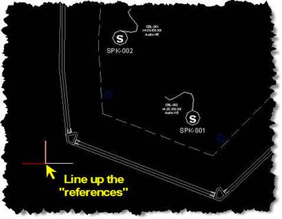
32)Line up the “reference shape” with the “reference block” so that their corners meet.
![]() The reason for this step is when you save the Visio drawing as an AutoCAD drawing (upcoming steps), only the Visio shapes will export, not the floor plan. The architect will use this “reference shape” to line up this drawing over the original AutoCAD file inside of AutoCAD.
The reason for this step is when you save the Visio drawing as an AutoCAD drawing (upcoming steps), only the Visio shapes will export, not the floor plan. The architect will use this “reference shape” to line up this drawing over the original AutoCAD file inside of AutoCAD.
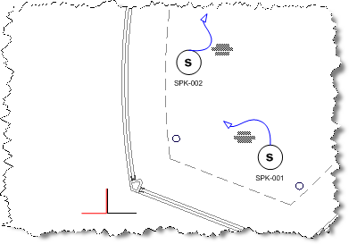
33)Add Visio shapes to the drawing page. In this case I added some speakers and wire.
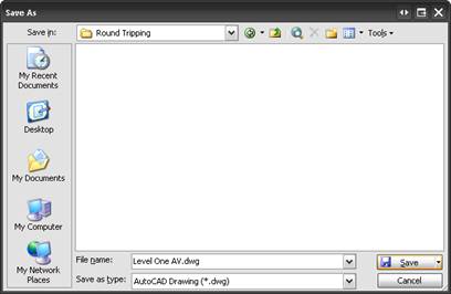
34)Save as a DWG by selecting File->Save as… and selecting AutoCAD Drawing from the Save as type: dropdown.
![]() If you are using a title frame shape in Visio, you may want to remove it from the Visio page before saving the file as an AutoCAD drawing.
If you are using a title frame shape in Visio, you may want to remove it from the Visio page before saving the file as an AutoCAD drawing.
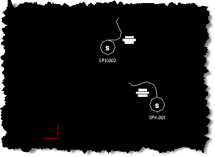
This is the file that you would send back to the architect. The Drawing only contains the Visio shapes that you added, not the original floor plan:
Externally Reference (Xref) the Visio Created DWG to the Original DWG
35)Open the original AutoCAD file in AutoCAD
36)From the menu bar select Insert->External Reference…and Browse to the file you just saved from Visio. Click [Open]. The External Reference dialog will open.
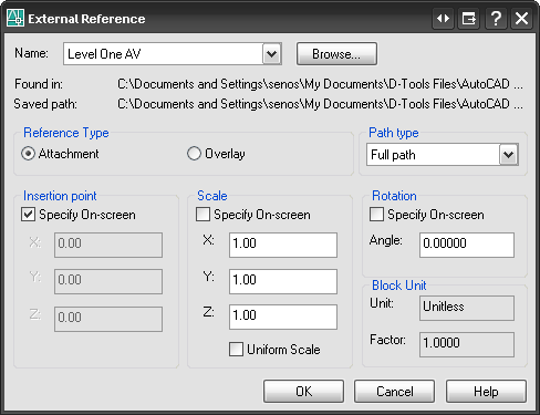
37)Check the Specify On-screen dialog then click [OK]. You will need to point the cursor to the matching CAD reference point.
38)Verify that the reference points line up. You may have to move the inserted xref layer to line up the reference points.
The reason that will have to move line up the “references” is because Visio’s “0,0,0 point” (technically just a 0,0 point in Visio) is always at the lower left corner of the drawing page while the AutoCAD “0,0,0 point” can be set.
- © Copyright 2024 D-Tools