Points
Table of contents
Details
Points are a concept in SI that allows you to add a designation of "action needed" or "functionality" to an input/output for a product. Labor may or may not be associated with a Point. Data will be stored for the product at the Project level and can be displayed on schematic pages in Visio.
Points are not enabled by default so you must choose to enable them:
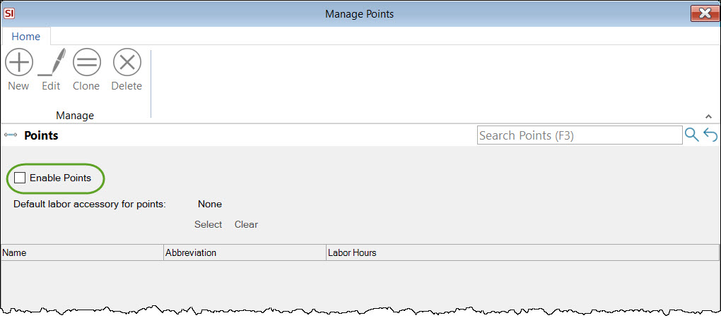
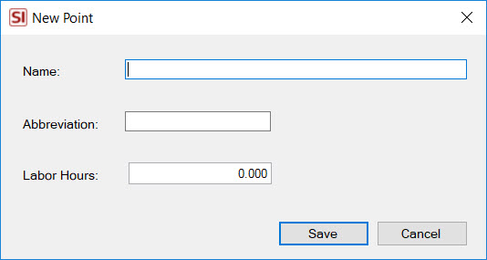
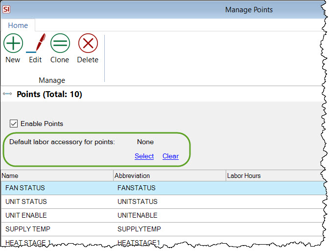
Once enabled, you can create your default list of Points. The fields available are shown below. You are required to enter a Name and Abbreviation (defaults to the first ten characters of the Name). The Labor Hours are optional.
You can also set up a default Labor Item for Points.
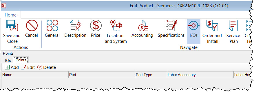
Adding Points to a Product
Within a Project, open the Product for edit and click the I/Os tab, then the Points tab:
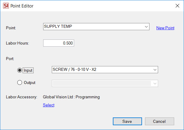
When you click Add the following dialog will open where you will select a Point and a Port (I/O). You can modify the default labor hours and you can change the default Labor Item if desired.
If you have chosen to associate a Labor Accessory to your Points, once you save the Product the Labor Item will be added as an Accessory to the Product. If more than one Point uses the same Labor Accessory, the Labor Hours will append the same Labor Item vs. adding a new one. In the example below, two Points were added to the Product, one with one hour assigned to it, the other with half an hour assigned to it, both assigned to the Labor Item "Global Vision Ltd : Programming". Only one Labor Item was added and the Labor Hours field is set to 1.5 hours.
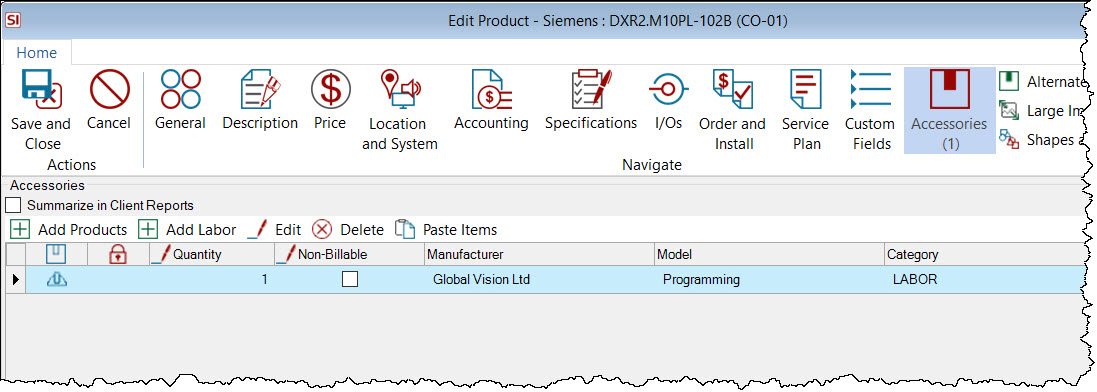
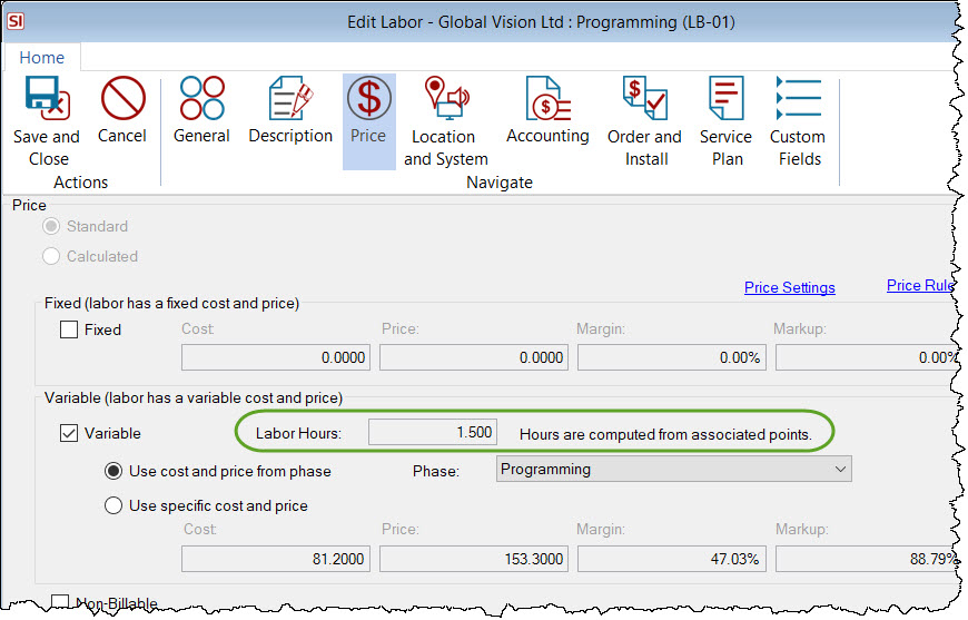
Notice that Labor Hours field is locked for edit. This is so if a Point is removed from the item, the hours will decrease and remain accurate.
Schematic Shape in Visio
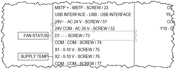
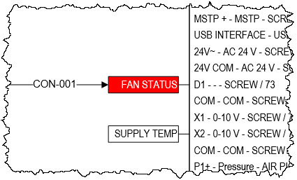
When you drag products with Points associated with them to a schematic page in Visio the Points will display next to the I/O on the shape.
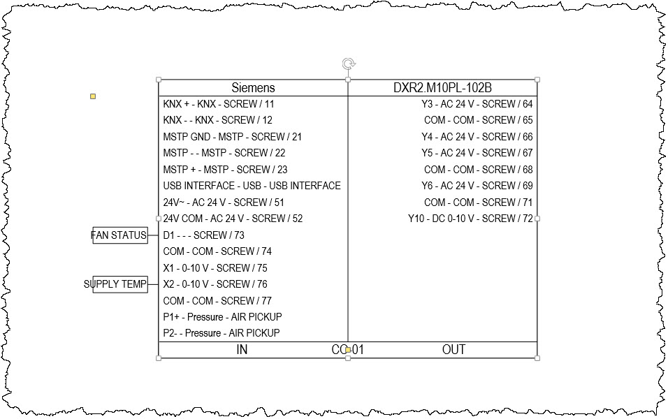
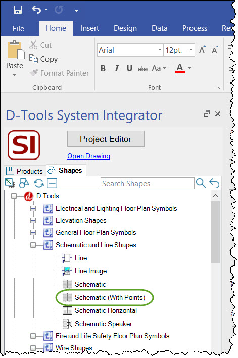
When Points are enabled, the Schematic (with Points) shape will be used vs. the Schematic shape:
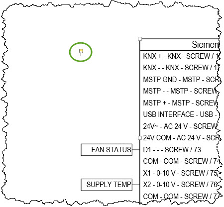
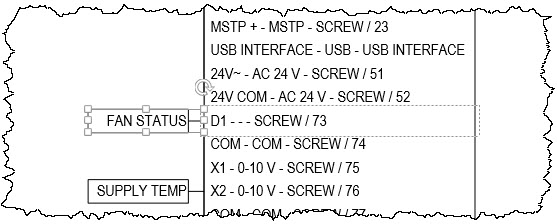
There is a yellow handle that allows you to re-size the surrounding box to accommodate the length of your text. This handle applies to all Points on each side of the shape:
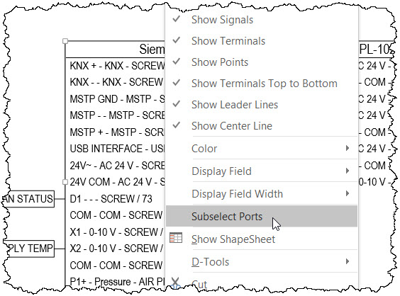
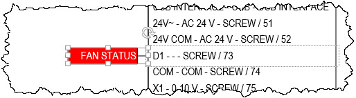
If you want to change the fill color or text color of the Ports or Points, right-click the shape and select "Subselect Ports":
You must first click so that the Port is selected.
You can then select the associated Point:
You can then change the fill and text color for the Point:
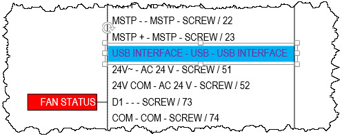
When the Port is selected, you can also change the fill and text color, regardless of whether the Port has Point or not:
SI Wire Shapes connect directly to the Point vs the Port:
Reporting
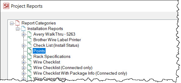
There is an installation report named Points that displays Points and you can always create your own custom reports.
- © Copyright 2024 D-Tools