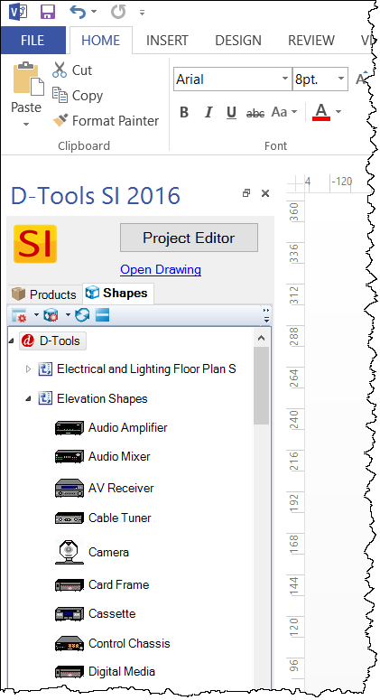
Elevation Shapes
![]()
Details
Elevation shapes are shapes that scale automatically based on the dimensions of a Product and are located in the Elevation Shapes Visio stencil.
Shape Data Window
All user adjustments are available in the Shape Data window.
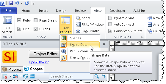
Most used adjustments can also be access by Right-clicking on a shape.
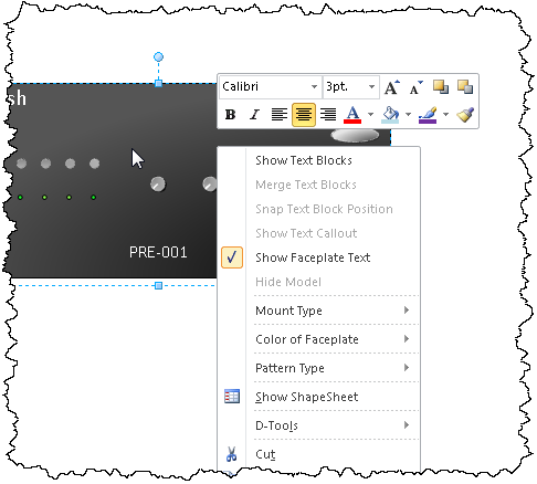
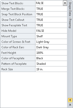
Show Text Blocks: This will show or hide the text block in the middle of the shape. This text block can be moved outside of the shape by moving the little yellow dot in the middle of the shape. Default is set to True.
Merge Text Blocks: You can break out the text block into separate Manufacturer, model and Component ID text blocks with separate movement options. Default is set to True.
Snap Text Block Position: You can have the text snap to specific areas on the shape or if you turn it off you can free form the text. Default is set to True
Show Text Callout: This displays a line that connects the text to the shape. Default is set to True.
Show Faceplate Text: Faceplate text is smaller text that stays within the shape and is designed to mimic the look and feel of actual manufacturer equipment. Usually used with the Text Blocks set to False. This is handy for creating photo real shapes.Default is set to False.

Hide Model: This will hide the model on both the text block and faceplate text. Good for hiding info on jobs that could get shopped.
Mount Type: There are four different mount types:
- Rack: Show ears, no feet, hide feet. If the Rack Mounted check box is checked in the specifications section of the Product Editor (double-click on a shape) then the Mount Type will be set to "Rack" on drop.
- Shelf: Hide ears, has feet, show feet
- Faceplate: Hide ears, has feet, don't show feet (this setting is used for items that go in a rack with a custom cut faceplate)
- None: Hide ears, no feet, hide feet (this setting is generates a generic, scale box shape)

Color of Screws & Feet: Easily change the color of the screws and feet on the shape
Color of Rack Ears: Easily change the color of the rack ears
Feet Height: The feet in these shapes automatically adjust based on the height and the width of the parent shape. However there are edge cases where the shape just does not look right with too big or small feet. It is kind of nit-picky but we decided to give the user the ability to fine tune the feet height to make the shape look better. Default is set to 100%
Color of Faceplate: Easily change between black, white and three shades of gray. There is some code in the shape that will turn the text black or white automatically depending on the faceplate color. Nice feature for creating photo real shapes. Default is set to White.
Pattern of Faceplate: Most of the current D-Tools shapes have a subtle shading that makes them look like they are lit from the top left. This option allows you to turn it on or off. Default is set to solid.

Rack Size: While most electronics are made for 19" racks there are some edge cases that use half rack and 23" rack sizes. Changing this will only affect shapes that have Mount Type set to Rack by changing the rack ear size based on the overall width of the device. These match up with the new equipment rack shape detailed below. Default is set to 19"


Missing Dimensions
Elevation shapes have a feature that deals with the long-standing issue of what happens when there are not dimensions associated with the product. In previous versions of D-Tools if there was a missing height/width dimension in the data then the shape would render effectively invisible.
To solve this issue we added some code to all of the elevation shapes that will render a missing dimensions graphic if either the height or width of the object has a zero value. If you drop a shape on to a page and you see the warning below all you have to do is double-click on the shape to open the product editor, go to the specification tab and enter in the correct dimensions.

Side View
This shape responds to the Height and Depth dimensions of the specific product. Again a pretty simple shape with the same movable text options as the other shapes. This one can be used as a stand alone shape or it can be used as a functional copy (same component ID) by using the right-click D-Tools->Shape->Generate Side View. If you toggle the Rack Mount option to TRUE you will not see the feet.

Equipment Rack
This is a unique and complex shape that will automatically draw just about any 19", 23", or half equipment rack with just the overall width, overall height and number of rack units from the database. It has built-in connection points at each 1.75" rack space and all of our elevation shapes and designed to "snap" into place at these 1.75" increments. Same text options as the other shapes and you can also change the color and adjust the headers with the shape data window. The header adjustment is for racks that are not symmetrical on the top and bottom.
We added a Shape Data UI for Rack Style so this same shape could be used for 19", 23" and Half racks. Default is 19".

- © Copyright 2024 D-Tools