Pinout Shape
Table of contents
Details
The Pinout shape in Visio is intended to give a visual representation for each "conductor" of a wire/cable. This feature works with the Finish Wire shape in Visio, commonly used on schematic pages.
The Pinout Reference ID and the page name it is on will display in a callout on the Finish Wire shape, near the "From" or "To" end of the wire shape. In the example below the callout is on the "To" end of the wire
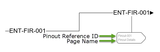
The Pinout Reference ID is automatically generated but can be modified in the Shape Data window, see below.
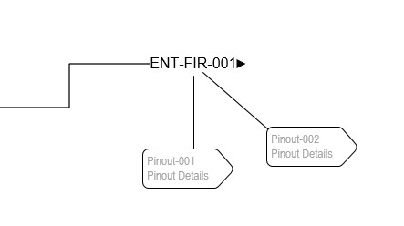
You can add more than one link to pinout shapes on each end of the wire if needed, e.g. there are six conductors in a wire and four go to one device and the other two go to another device:
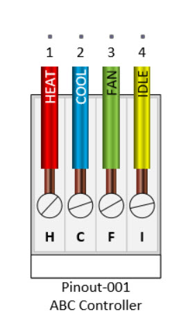
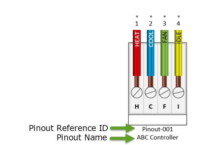
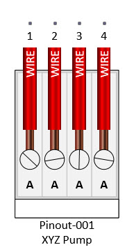
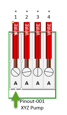
The Pinout shape displays the Pinout Reference ID and the Pinout name by default:
Steps
- On a schematic page, right-click a Finish Wire shape mouse over D-Tools->Pinout Legends and you will see three options: Link From Wire Connection to Pinout, Link To Wire Connection to Pinout, Convert Pinout to Master Shape.
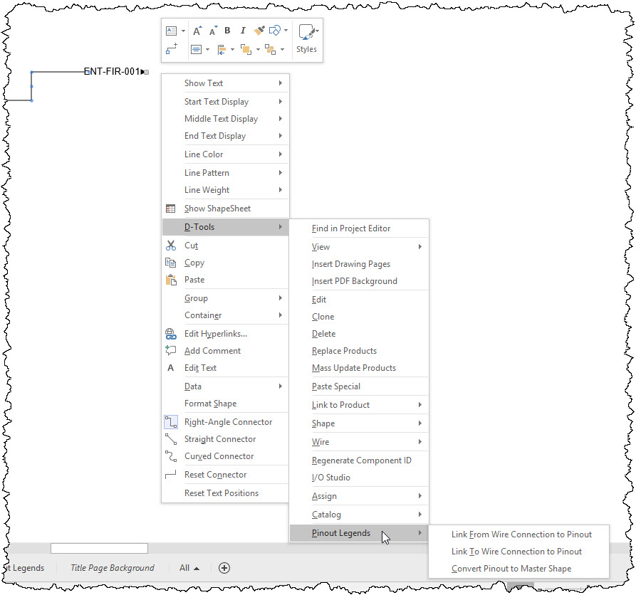
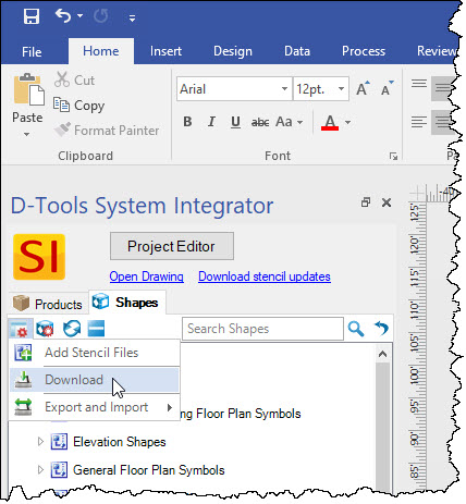
Note: If you don't see these options, click on Manage Stencils in your Stencil Tree and choose Download. This will open a form showing new and updated stencils that you can download. You will want to to download the Wire Shapes stencil.
The "From" and "To" correspond to the ends of the Finish Wire shape:
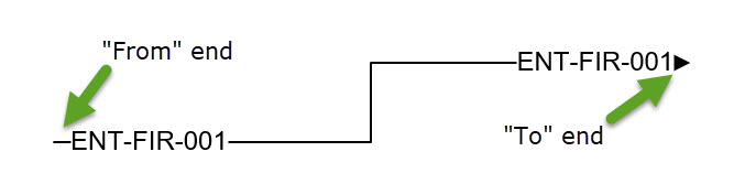
Note: The "From" end of our wire shapes is intended to be the Headend end of the wire.
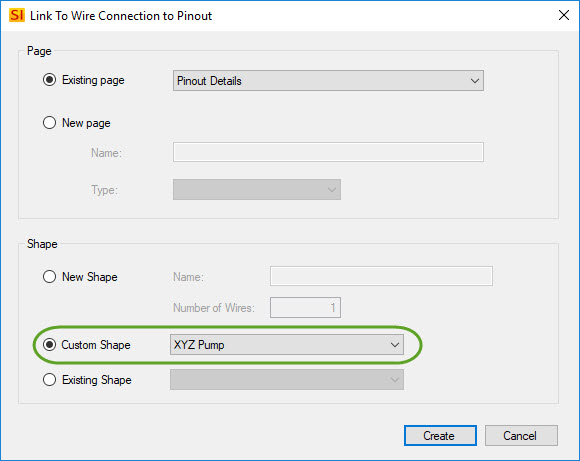
- When you select either the "From" or the "To" options, the following form will open:
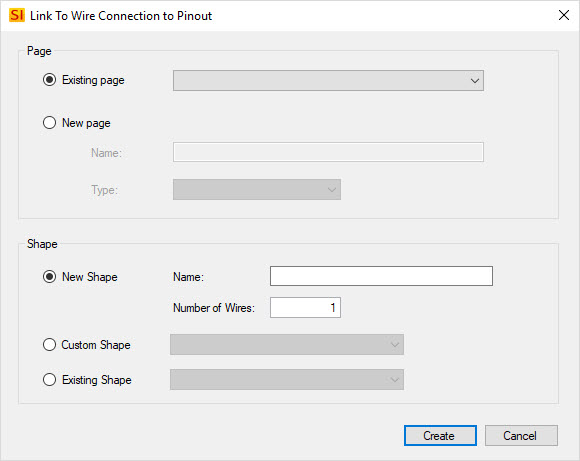
Page
Here you can choose to add the Pinout shape to an existing page or you can create a new page. When creating a new page you are required to choose a "Type": Line, Elevation, Plan, or Schematic. It doesn't matter what you choose if you are planning to keep the page strictly a "pinout legend" page, but if you plan to drop Product shapes on this new page then you would choose the page type to correspond with the shapes you want for the Products.
Shape
New Shape - This will create a new Pinout shape with the number of wires you specify. A name is required.
Custom Shape - This will allow you to choose from any pinout shapes that you have converted/saved as a Master Shape. See below for details.
Existing Shape - This will allow you to select an existing pinout shape that is on a page in the Visio drawing.
- When you click the Create button, based on your selections a Pinout shape will created or linked to the "From" or "To" end of the Wire shape. A new page may be created based on your selections as well.
Pinout Shape
In the example below, the "New Shape" option was selected with four wires:
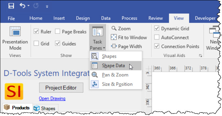
You can modify the text that displays on each wire/conductor, the Code (default is "A"), and the fill color. For two of these modifications you will need to display the Shape Data window in Visio via View->Task Panes->Shape Data:
The Shape Data window for the Pinout shape is shown below:
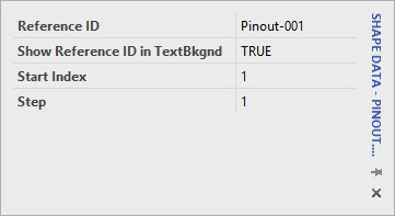
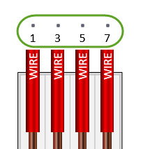
Here you can change the Reference ID, choose whether to display the Reference ID on the shape, change or start index, and choose the "step" between the numbers. For example, if the pinout you are creating has only odd numbers, changing the step to "2" will accomplish this:
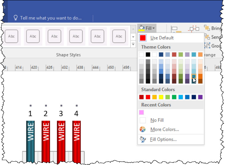
You can select individual wires/conductors on the shape by clicking on them. A border will display around the shape but there will also be a border around the selected wire:
To change the color, use the Visio Fill tool:
To change the Name or the Code, use the Shape Data window for the selected wire/conductor:
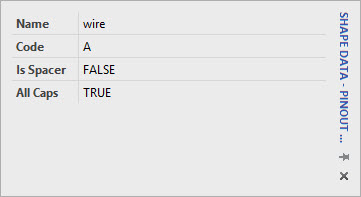
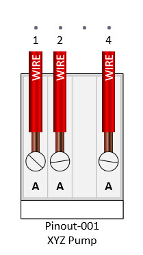
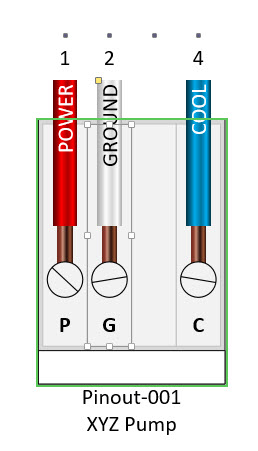
Here you can choose whether the text will display in all caps. You can also choose whether a wire is a spacer or not. A spacer will leave a "gap" in the shape for any wire/conductor marked as a spacer. In the example below the third wire from the left was marked as a spacer:
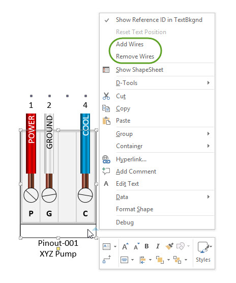
You can add wires/conductors to the shape after is created a few ways. The first is to select the entire shape by clicking in the name, then right-clicking. You have the option here to add or remove wires:
You can also add wires when you mouse over the Pinout shape on either side of a selected wire and see a blue arrowhead. When you click this arrowhead a new wire will be inserted:
Moving the Shape
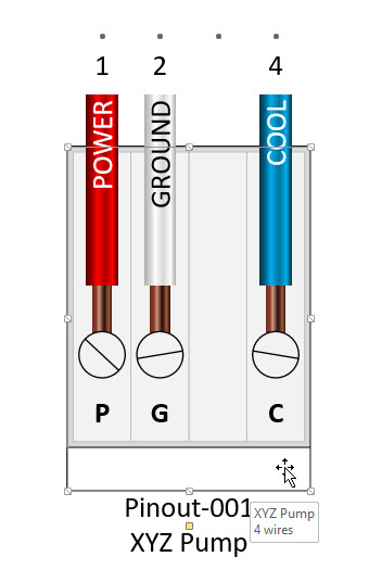
New Pinout shapes will always drop in the center of the chosen page. So after you create each one you should move it somewhere else on the page to avoid the shapes stacking on each other. To move the shape, make sure you select the entire shape by clicking on the name (vs. selecting an individual wire as shown above), then drag to where you want to place it:
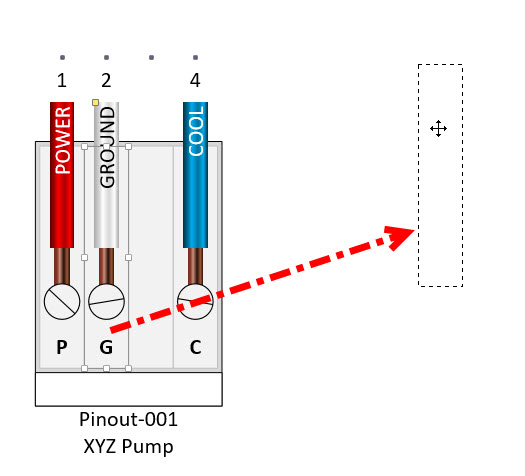
If an individual wire/conductor is selected, you may accidentally drag it out of the Pinout shape vs. moving the shape:
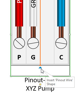
If this happens you can drag wire/conductor back on top of the shape. Wait until you see an orange line appear showing where the wire/conductor will be inserted and then release the mouse button:
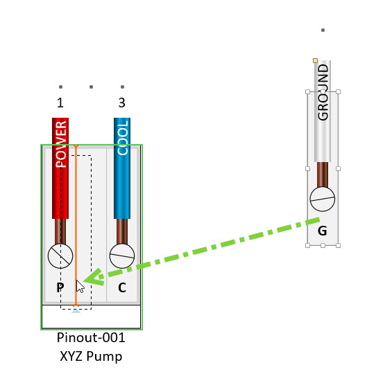
The wire/conductor will insert back into the Pinout shape:
Create Master Shape
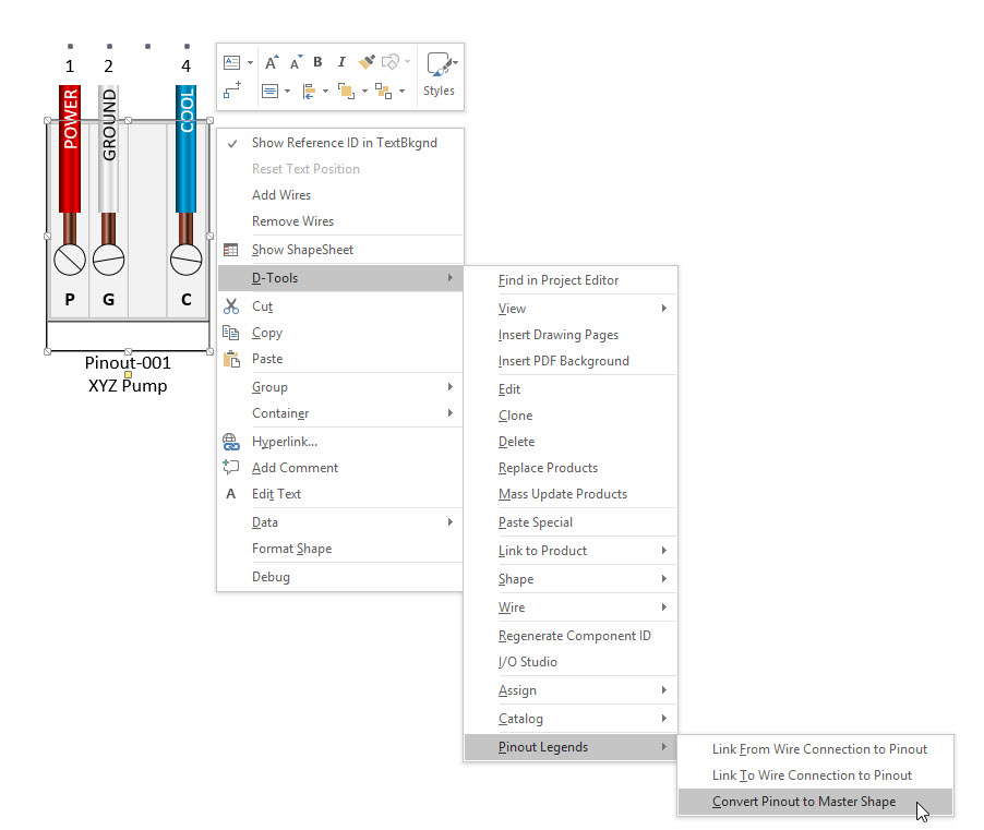
It is likely that once you modify a stock Pinout shape to represent a specific pinout that you will want to re-use this Pinout shape on future drawings. To create a Master Shape to re-use, select the Pinout shape and right-click and choose D-Tools->Pinout Legends->Convert Pinout to Master Shape:
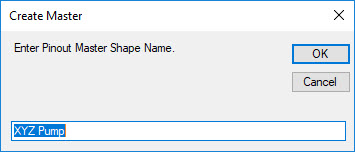
You will be prompted to name the shape. The current name of the shape will be displayed by default but you can change it whatever you want:
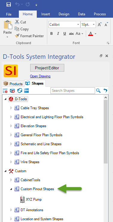
The shape will be added to a stencil named "Custom Pinout Shapes" that will display in your Stencil Tree under "Custom":
While these custom pinout shapes can be dragged over a Visio page, we recommend that you use the right-click options "Link From Wire Connection to Pinout" and "Link To Wire Connection to Pinout" to add these to your drawings:
- © Copyright 2024 D-Tools