Schematic
Table of contents
Schematic Page Type
The schematic sheet type is used to create the wiring diagrams for systems within a Project. An example of a Schematic drawing sheet is below:
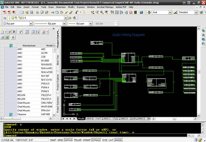
The blocks intended for use on this drawing sheet type list the inputs and outputs for the Product.
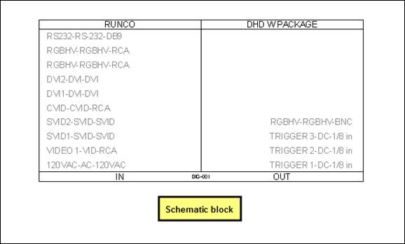
Schematic blocks size vertically automatically based on the number of inputs and outputs for a Product. Each input and output listed has a “connection point”.
Wire and Cable shapes are used on this page to connect Products. The connections made with Wire and Cable shapes are recorded for reporting. Example reports are the Brother Wire Labels and the Wire Connection reports. For a complete description see Reports.
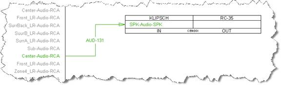
![]() The default color for an unconnected wire on the Schematic sheet is red. Once the wire is connected between two Product blocks, the color is green.
The default color for an unconnected wire on the Schematic sheet is red. Once the wire is connected between two Product blocks, the color is green.
The wire and cables block that drops by default on a schematic sheet is the Schematic block:
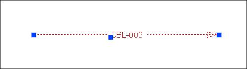
There are selection points at each end of the block, one in the middle, and one on the text label.
- © Copyright 2024 D-Tools