Using Layers in Visio
Table of contents
Using Layers in Visio
Effectively using layers in Visio can allow you layout multiple systems on one drawing page and then toggle between turning layers on/off depending on who is viewing the drawing. This could allow you to have just one drawing page for each floor plan within your project that contains all systems for the project, e.g. security, lighting, A/V.
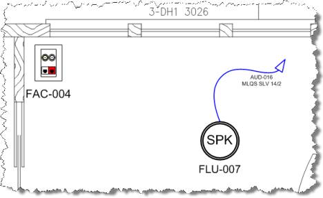
By default, SI 5 shapes are assigned to a layer based on the Category name of the product they are associated with. In the example below, there are products from the Plates, Speakers, and Wire and Cable Categories.
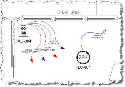
In addition to those shapes, there is an AutoCAD drawing inserted on the page. To view the layers, right-click anywhere on the drawing page and select View->Layer Properties. The Layer Properties form opens.
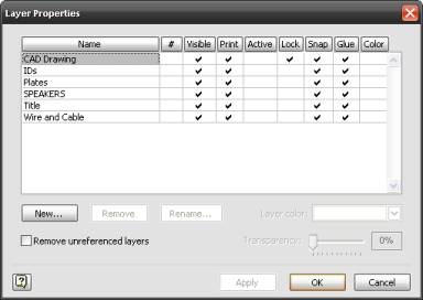
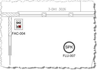
On this form you can lock layers as well as choose what layers are visible or not. You may wish to show a client the drawing without the wires showing. To do this, uncheck the “Visible” box for the Wire and Cable layer. The drawing will now display without the wires.
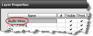
You can create your own layers and assign shapes to the layers. For example, you may want each type of wire to be on their own layers, e.g. – audio, video, control, etc. To this, open the Layer Properties form and click [New…]. Type in a name and click [OK]. The name will now appear in the Layer Properties form.
Click [OK] to close the Layer Properties form. Select the shape(s) that you wish to assign to a new layer. Right-click and select Format->Layer. On the Layer form, uncheck the Wire and Cable layer and check the layer that you created then click [OK]:
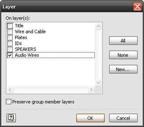
Now you can choose to just display audio wires using Layer Properties form:
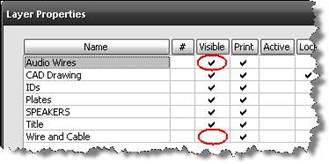
Aside from the “Visible” column, you can use the “Print” column to choose what prints or use the “Color” column to change the color of all shapes for a particular layer.
- © Copyright 2024 D-Tools