Schematic Shapes

Details
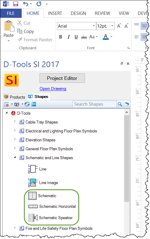
Schematic shapes list the inputs and outputs for a device and are located in the Schematic and Line Shapes Stencil:
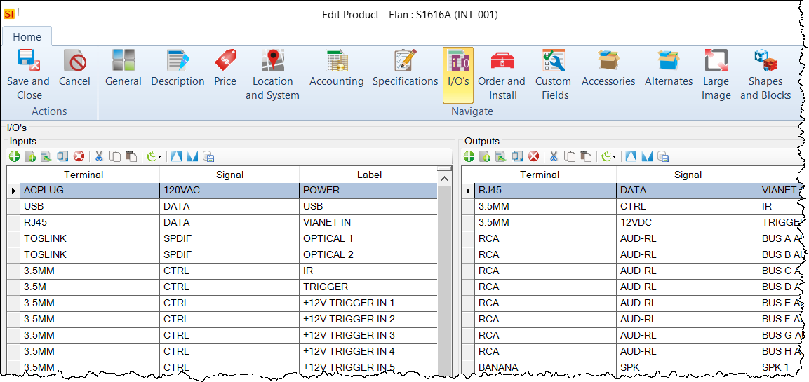
The data for these shapes is pulled from the I/O's tab:
Schematic
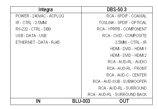
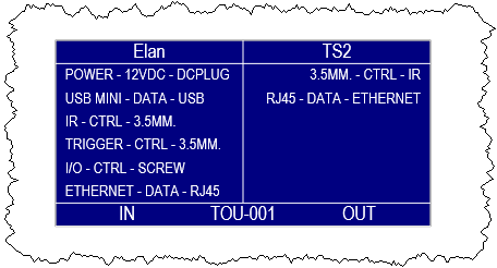
The default Schematic shape displays the Inputs and Outputs for the product based on what has been entered in the I/O Studio.
Schematic Horizontal
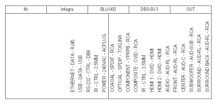
There is also a Schematic Horizontal Shape:
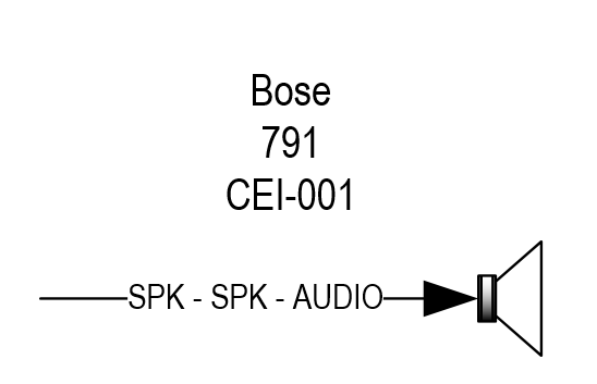
Schematic Speaker
Speakers have a unique schematic shape:
Connection Points
Each Input/Output on the shape has a connection point and are intended to be "connected" to other items with our Wire Shapes, specifically the Finish Wire shape.
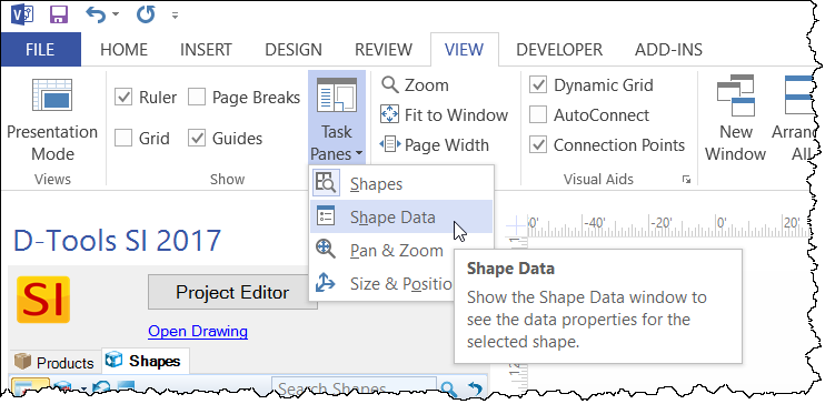
Shape Data Window
All user adjustments are accessed through the Shape Data window. To display the Shape Data window, click the View tab then select "Shape Data" from the Task Panes dropdown:
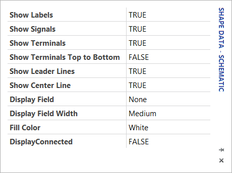
These are the Shape Data fields for Schematic Shapes:
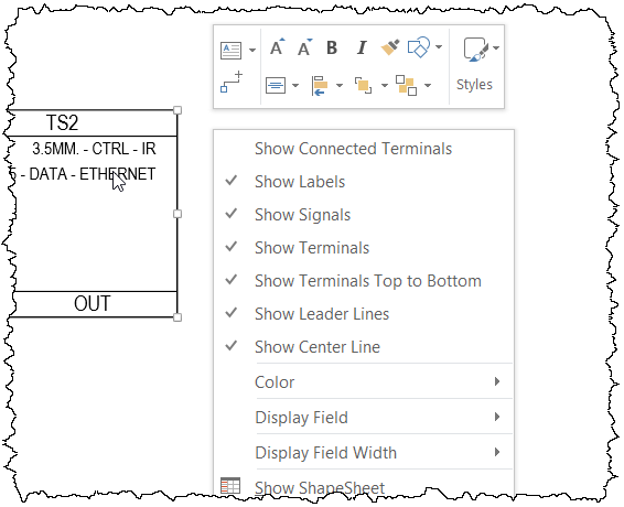
The most common used settings can also be accessed by right-clicking the Shape:
Show Labels: By default, each Input/Output lists the Terminal, Signal, and Label fields. Here you can turn off the Label fields.
Show Signals: By default, each Input/Output lists the Terminal, Signal, and Label fields. Here you can turn off the Signal fields.
Show Terminals: By default, each Input/Output lists the Terminal, Signal, and Label fields. Here you can turn off the Terminal fields.
Show Terminals Top to Bottom: This will flip the orientation of the Inputs/Outputs on the Shape.
Show Leader Lines: When displaying text fields and you use the handle to move the text, this option displays a line. See Display Field below.
Show Center Line: This allows you to turn off the center line on the shape. Default is True.
Display Field: This allows you to add a text field beneath the shape. The options are: ComponentID, Category, Subcategory, Model, Manufacturer, Installation Price, MSRP, Phase, Short Description, Long Description, Volts, Amps, Watts, BTU, IP Address, Serial Number, Part Number, Location, System, and Custom Fields 1-14. See below for more details.
Display Field Width: This allows to choose between Auto, Narrow, Medium, or Wide to determine how the Display Field, well, displays. See below for more details.
Fill Color: This allows you to change the fill color of the shape.
DisplayConnected: This will collapse the shape to only show the terminals that have a Wire Shape connected to them. Default value is False.
Display Field
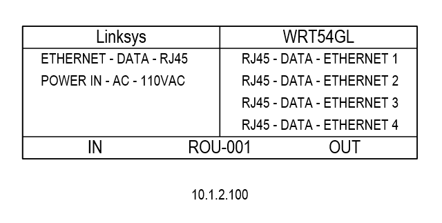
Below is an example of an item displaying the IP Address field:
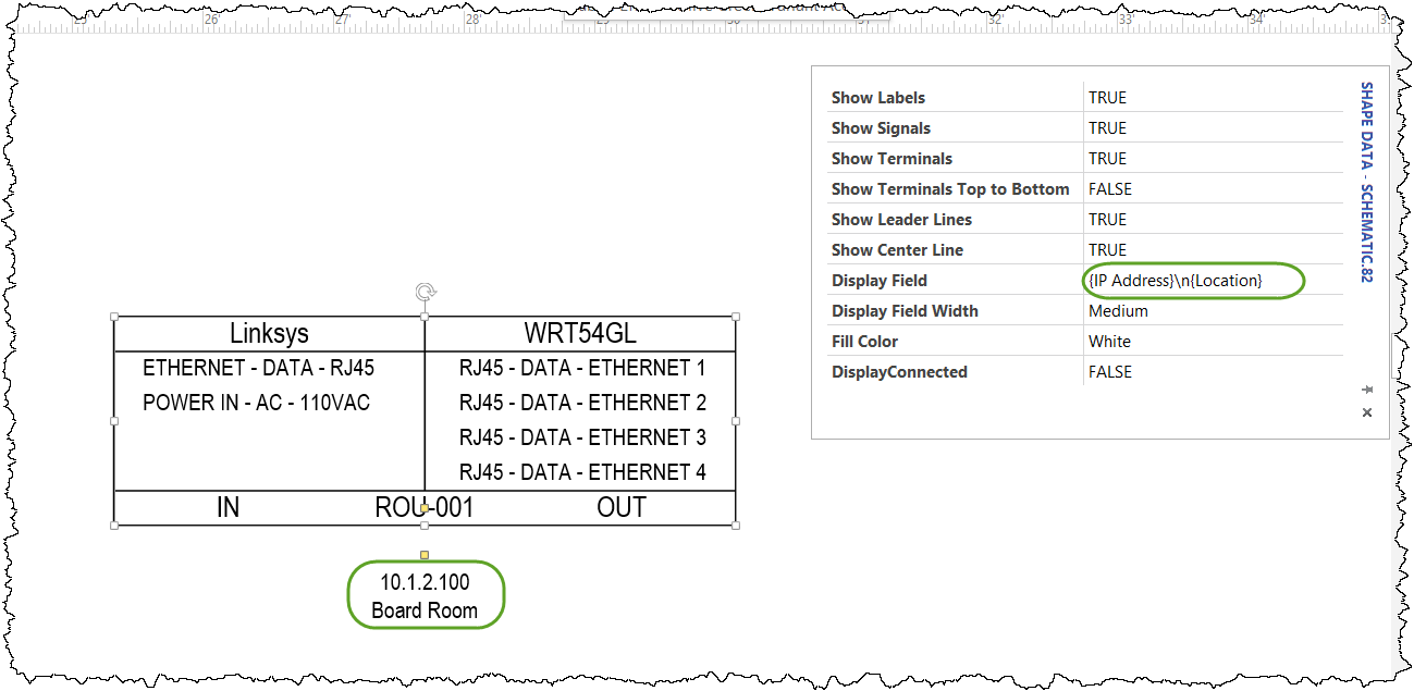
If you want to add multiple fields you can manually type in additional field names in curly brackets - {field name} - separated by a forward slash and an n - \n, in the Display Field box in the Shape Data window.
In the example below I selected IP Address as the first field and then typed in the following - \n{Location} to display two fields:
- © Copyright 2024 D-Tools