Stencils and Shapes
Overview
This explains the stencils and shapes available in FreeTools.
Details
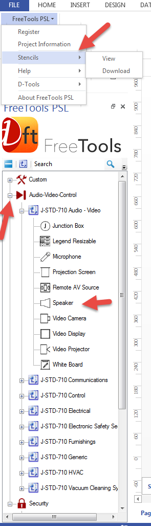
FreeTools comes with a stencil tree instead of the traditional Visio stencils. This was done so the user could have all relevant stencils available at once. When you open up or start a new FreeTools drawing the current stencil sets will be available in the stencil tree on the left. You can click the plus "+" to open or close the categories and the individual shapes in each stencil. You can download additional stencils by going to the top level Visio Add Ins menu and clicking the stencils option.
Details
FreeTools uses Visio stencils to store the industry specific symbols. Each stencil represents a specific category of products that the symbols represent. While the symbols can look different they are all based on the same infrastructure and share common attributes. Lets take a close look at the keypad example below. This keypad symbol is based on the J-STD-710 specification.
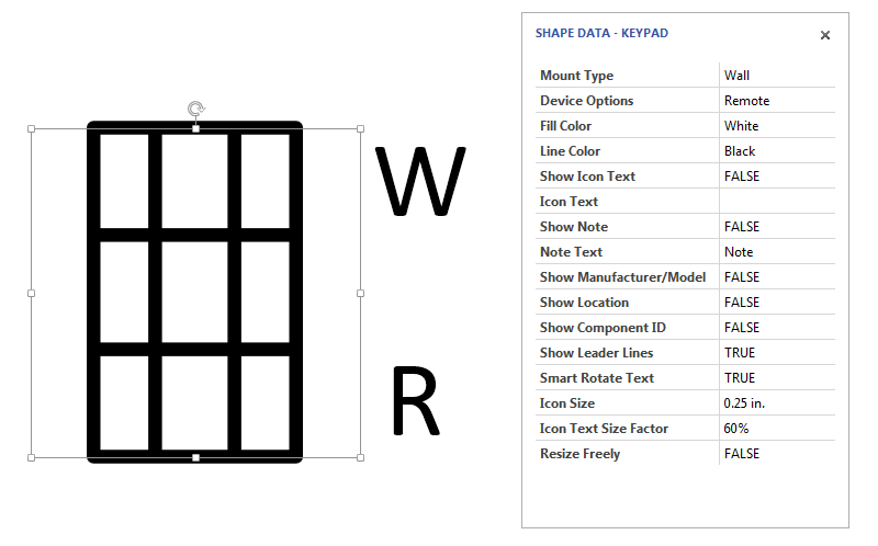
Based on the specific industry specification some shapes have textual abbreviations for common features for that specific device. The top right text feature is the mount type the bottom right is the device option. These are available to change from the Visio shape data UI or by right clicking on the shape. In this example the keypad is a wall mount (W) and a Remote (R)
FreeTools Symbols In Depth
The best way to explore the features of these symbols is to activate the Visio shape data UI. This is done by right clicking on the symbol and choosing Data->Shape Data. This will open up the shape data window on the far right of the screen by default but can be dragged anywhere on the screen.
Mount Type is accessed via a drop down menu of all the mount types as dictated by the industry specifications. Default is None.
Device Options are specific to each device and are based on the industry specifications. Default is None.
Fill Color is a pre programmed palette of custom colors that can be accessed by a drop down menu. Default is white.
Line Color allows the user to customize the line color from the same color palette as the fill color. Default is black.
Show Icon Text is mainly used by D-Tools SIX software. Default is false.
Icon Text allows the user to add freeform text to the icon text. Mainly used by D-Tools SIX. Default is blank.
Show Note is a toggle that is set to true will show a note that is attached to the symbol. Default is false.
Note Text allows the user to add free form text to that note if show note is set to true. Default is blank.
Show Manufacturer/Model is used by D-Tools SIX. Default is false.
Show location is used by D-Tools SIX. Default is false.
Show Component ID is used by D-Tools SIX. Default is false.
Show Leader Lines turns the line connecting the note and component ID on or off. Default is false.
Smart Rotate Text keeps the text readable no mater the orientation of the symbol. Default is true.
Icon Size will change the size of the symbol. Default is .25 in.
Icon Text Size Factor will change the size of the icon text. Mainly used by D-Tools SIX.
Resize Freely if set to true will allow the user to grab a control handle and resize the symbol. If set to false it will default to the icon size field. Default is set to false.
D-Tools Extras Stencil
Along with the industry standard symbols FreeTools includes a D-Tools extras stencil. This stencil contains the following useful shapes for general project documentation.
Bulk Wire
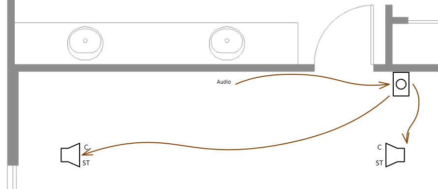
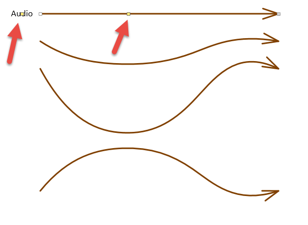
The bulk wire shape is designed to "glue" to the connection points of any of the symbol shapes to represent a wire run either between components or a run from a headend to a component. Take a look at the volume control documentation below. Notice the top brown wire is going into the volume control on the wall with the label "audio" at the tail of the wire. What this means is that the wire is coming from the audio headend and going to the volume control. The arrow direction denotes signal flow. You can also see that the signal is coming from the volume control to the room speakers.
Like the symbol shapes, the Bulk Wire shape has a number of right click options and Shape Data options detailed below:
Show Text will show or hide all the text in the shape. Mostly used by D-Tools SIX. Default is true.
Merge Text Blocks is used by D-Tools SIX. Default is false.
Show Component ID is used by D-Tools SIX. Default is false.
Show Model is used by D-Tools SIX. Default is false
Show Headend will show or hide the headend text at the tail of the wire shape. Default is true
Show Type is used by D-Tools SIX. Default is false.
Line Color allows the user to pick a color to represent a signal type. Default is black.
Line Weight allows the user to select a specific line weight to represent a specific signal type. Default is 3/4 pt.
Line pattern allows the user to change from a solid to a dashed line. Default is solid.
Arrow Style allows the user to pick from three different types of arrow heads to represent different signal types. Default is open.
Headend Text is where the user enters the specific headend data for that specific wire. Default is blank.
Text Size Factor allows the user to change the text size of the headend text. Default is set to 100%
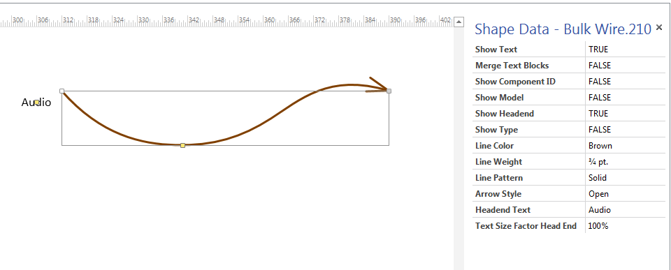
Some of these Shape Data options are available by right clicking on the shape as well. Additionally there are two control handles on this shape represented by a yellow square, see arrows above. The control handle by the headend text allows the user to move that text around the shape. The control handle in the middle of the shape allows the user to flatten or make the shape more round.
Text Call Out
Universal Dimension Shape
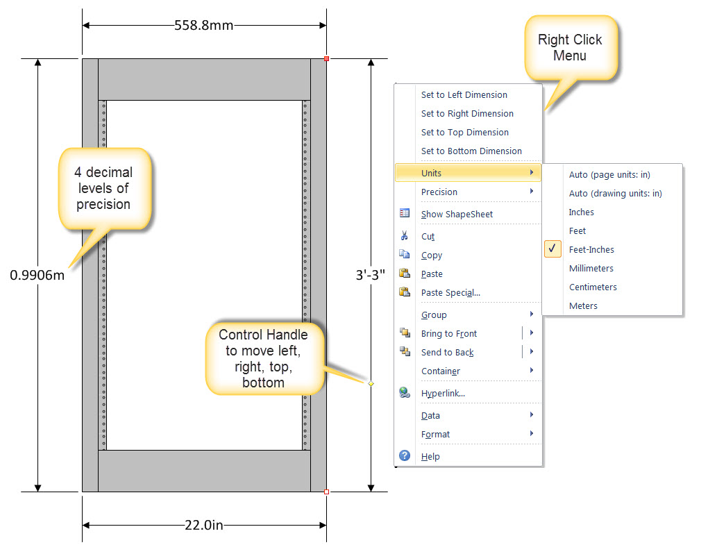
The single Universal Dimension shape works on all sides of an object you want to measure and works with all measurement units. In addition there are now up to 0.0000 user defined levels of precision. The previous dimension shapes required a separate shape for each side of an object and did not work well at metric measurement units.
How to use the Universal Dimension Shape
Drag on to the drawing page and attach the extents to a shape you want to measure. Explore the Shape Data UI and Right Click menu to set options. Use the control handle or the right-click Set Dimension commands to set the shape to the proper alignment. The default measurement unit settings are set to Auto (page units). This means that whatever the page is set to the shape will assume those properties. The default precision unit is set to 0.0. Both can be easily changed. See above.
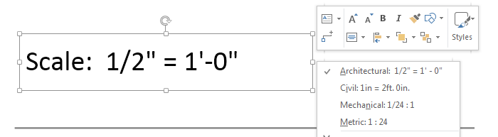
Drawing scale shape
In some cases you may have a background layer that is a different scale than the foreground layer you are working on. The title bar shape in the background layer will only display what the scale is on the background layer it is on. If you need to have an accurate scale of the foreground page drop this shape over the scale notation and it will automatically configure to the foreground page scale. There are right click options that allow the user to change the measurement units of the shape.
- © Copyright 2024 D-Tools