Linking Custom Blocks to SI
Overview
Custom blocks can be created within AutoCAD and then linked to SI products.
Steps
- Open AutoCAD outside of our program.
- If you have an existing block, open it in the Block Editor and then continue to step 7.
- Create a new .dwg file.
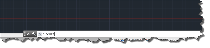
- Once the new drawing file is opened, enter “BEDIT” command to open the block editor.
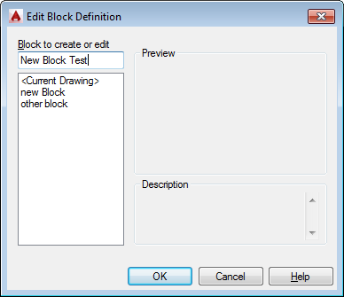
- Within the Edit Block Definition pop-up, type in the desired name of the block and click OK.
- Draw or insert the desired block.
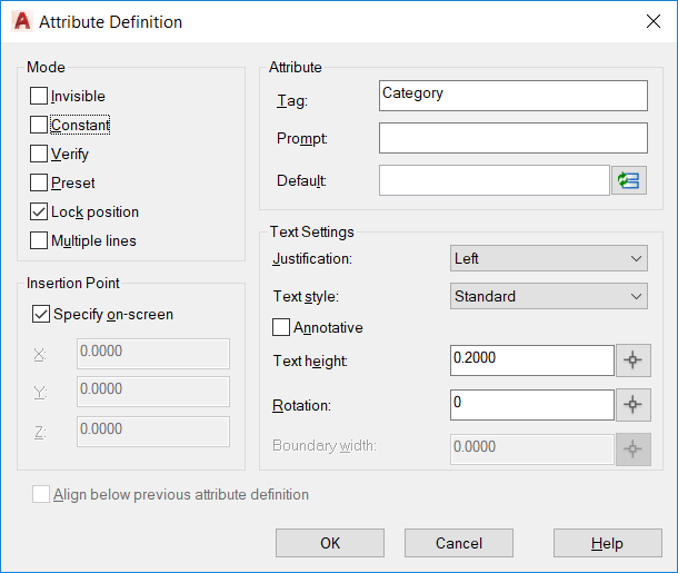
- Enter "ATTDEF" command to input the desired tag. The spelling of the tag name must be entered verbatim, see list below. Shown below the tag name "Category" is entered as this is a required tag, regardless of whether you make this attribute visible or not.
Tag Name List
Manufacturer
Model
Category (*required attribute)
Subcategory (or Type)
CategoryId (firt three characters of Category)
PartNumber (or SKU)
Quantity
ComponentID
SerialNumber
IPAddress (or IPAddress1)
IPAddress2
MACaddress1
MACaddress2
ProductDescription (or ShortDescription)
ClientDescription (or LongDescription)
MSRP
UnitCost
UnitPrice
UnitLaborHrs (or LaborHours)
InstallPrice (or InstallationPrice)
Phase
OwnerFurnishedEquipment
NonBillable
Location (this displays the full location path)
LocationShortName (this displays just the ultimate location name)
LocationNumber
System (this displays the full system path)
SystemShortName (this displays just the ultimate system name)
Height
Width
Depth
Weight
RackMounted
RackUnits
Amps
Voltage or Volts
Watts
BTU
Diameter
BulkWire
WireLength
HeadEnd
StartTerminal
EndTerminal
CustomField1 (Text) Fields 1 to 5
CustomField6 (Number) Fields 6 to 8
CustomField9 (Date) Fields 9 to 11
CustomField12 (Long Text) Fields 12 to 14
CustomField15 (List) Fields 15 to 18
CustomField19 (Boolean) Fields 19 to 22
CustomField23 (Hyperlink) Fields 23 to 26
- Place the attribute in the desired location.
- Repeat steps 7 through 8 to add additional attributes.
- Once all the changes have been made to the Block, enter command "BSAVE" to save the changes and close the Block Editor by entering command "BCLOSE". Multiple Blocks can be included within one drawing, but each block must have a defined attribute to be associated with SI.
- Save the Drawing and close the drawing.
- Open an AutoCAD drawing for a project within SI.
- In the SI window, click the Blocks tab, click the Manage Blocks button and select Add Block Files.
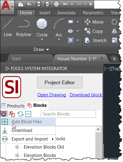
- Browse for the dwg file you just modified above and click OK. Your dwg file with your custom blocks will display within the "D-Tools" node.
- When a custom block is dragged to the drawing area, you will be prompted to select a product from your SI Catalog to add to the project.
- © Copyright 2024 D-Tools