Line View
Table of contents
Visio Line Page Type
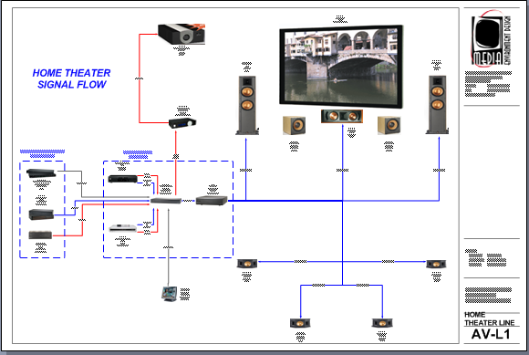
The line page type is used to create a flow chart of systems within a Project. An example of a Line Diagram drawing page is below:
The shapes that are intended for use on this page are either the default Line Image shape that populates with the Image that you have assigned to the Product or the Line shape:
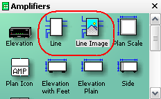
Line shapes are intended for use on a line diagram drawing page to provide a conceptual overview of the system. Line shapes are not to scale and can be resized. If you want to change the default shape that drops, see the Right-Click Options.
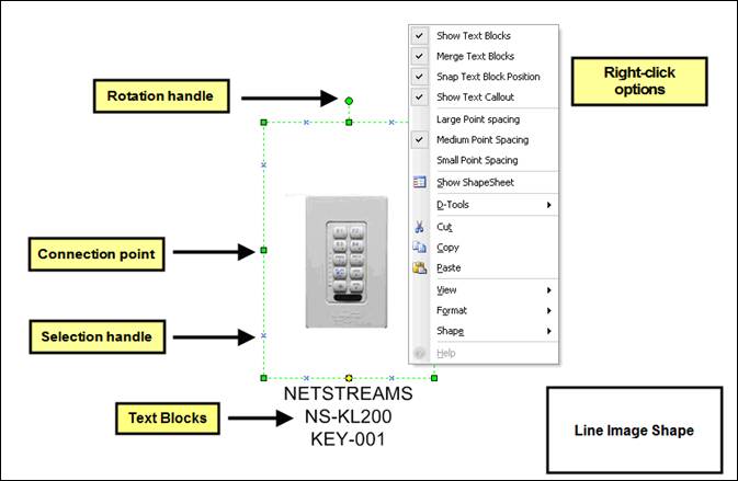
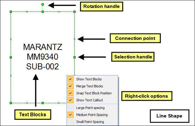
Right-click options specific to Line shapes
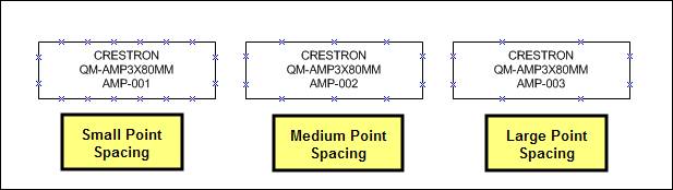
Large/Medium/Small Point Spacing: allows you to change how many connection points display on the shape.
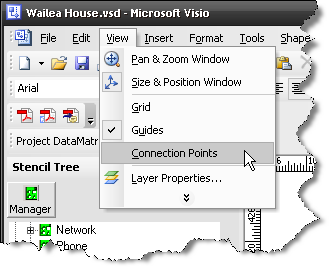
![]() If you do not see any Connection points, you can turn them on by selecting View->Connection Points:
If you do not see any Connection points, you can turn them on by selecting View->Connection Points:
The shape can be resized using any of the Selection handles. The Connection points are there for attaching line connectors between Products to show the signal flow of a system. Although you could use Wire shapes on this page, it is not necessary.
There a few options for adding line connectors. One option is to use the D-Tools created Line Connector shapes in the Wire and Cable Stencil:
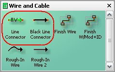
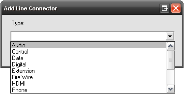
These line connector shapes are not linked to Products in the SI 5 database like the Wire shapes are but they are linked to the Type table for wire Products. When you drag and drop the Line Connector shape onto a drawing page, you will be prompted to pick a Type for the wire you are representing with this shape:
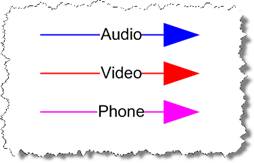
The colors assign based on this legend:
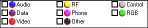
The color and the “Type” text will display on the shape:
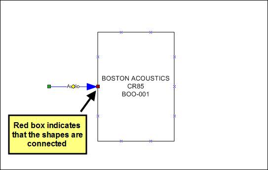
Each end of the line connector shape has a connection point that you can attach to a connection point on another shape:
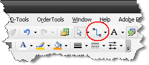
Another option for adding a line connector is to use the Visio Connector Tool function:
- © Copyright 2024 D-Tools