Home > SI 2015 Documentation > User Guide > Projects > Visio Interface > Visio Shapes > Wire Shapes > Create Graphic Line Ends
Create Graphic Line Ends
Create Graphic Line Ends

Details
This is how you can create and edit the line end shapes that come with SI 2015. Requires some basic to advanced Visio skills. There are two parts. 1: How to name and create a new line end. 2: How to distribute the new line ends to other users in your company.
How to create a new line end
- Start Visio in a new or existing SI 2015 project
- Open the Visio Drawing Explorer. Developer>>Drawing Explorer checkbox

- Right click on the Line Ends section and select New Pattern
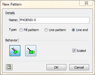
- Give the new pattern a name, in this case I am creating a 5 port phoenix connector. Make sure Line end and Scaled are checked and Behavior is selected as below.
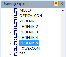
- Find the new shape name in the Drawing Explorer and double click on it to open the edit window.
- Using the Visio tools draw the shape you want represented. it is a lot easier to start with an existing line end and modify that one. Just open another line end and copy. In this case I am starting with the PHOENIX-4 Line end. The shape size should be around 4" wide and 1.5" tall but not super critical.
- When you get the shape the way you want it to look you need to flatten it so that it is just a single layer. This is done by selecting the entire shape and using Developer>>Operations>>Combine
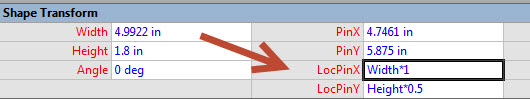
- Next you need to relocate the PinX to the right of the shape. This is done in the ShapeSheet Shape Transform section. Change the LocPinX formula from Width*0.5 to Width*1. This will align the shape to start where the line ends.
- Close the shape edit window and select save.
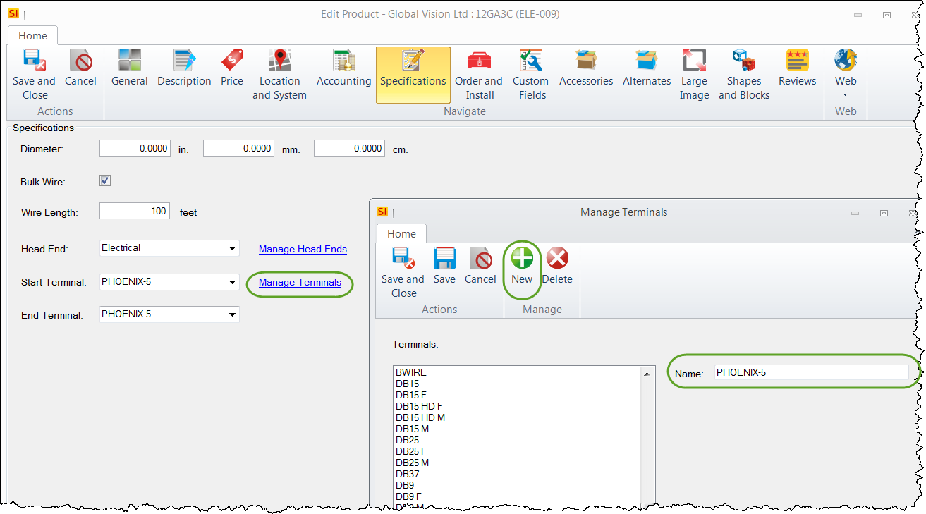
- Test the shape by dropping a finish wire on the page. Double click on the wire shape to open the edit product window. Go to the I/O's section. Add PHOENIX-5 to the Manage Terminals list. It has to be spelled EXACTLY the same as the shape name.
- Save and Close, Save and Close, Update and Close.
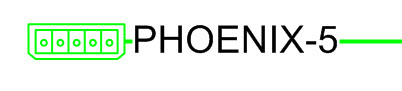
- If everything was done right you should have a new Phoenix-5 line end and text at the end of the wire shape.
How to distribute the new custom line ends
Visio custom line line ends can only exist in a drawing. In order to distribute we created some code that takes a special custom shape and uses that to populate new drawings at startup. Too complex to explain the why, but here is the how:
- Right click on the Wire Shapes section of the shape tree and choose Open Stencil
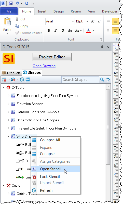
- You should see something that looks like this: Right click on the Wire Shapes Header and choose edit stencil
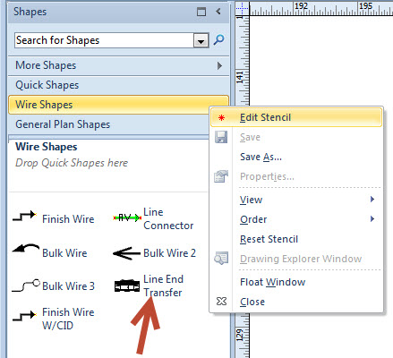
- Double click the Line End Transfer shape. This is just a container to hold the line ends. Expand that shape vertically so you can zoom in and see the individual connectors.
- Open the shape by Right Click>>Group>>Open Group
- Go to the last shape on the bottom and copy the last shape. Should look something like this:

- Right Click on the shape you just copied and go to Format>>Line
- Choose the new shape name you created from above for both the begin and end. Click OK.

- When you click OK you should see the new line end.
- Double click on the line in the middle, this will highlight the text. Change that to the proper name from above, in this case it is Phoenix-5

- Close the group window
- Close the shape window and click Yes on the update line end transfer. This will save the Line End Transfer shape to the stencil

- Save the stencil by clicking on the disc icon.

- Restart the current drawing or start a new drawing and test to see if it worked.
- © Copyright 2024 D-Tools