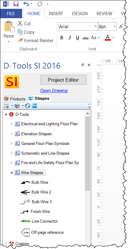
Wire Shapes
![]()
Details
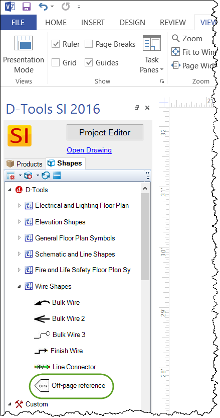
Wire Shapes are intended for use on the Plan, Schematic, and Line pages in Visio and are located in the Wire Shapes Stencil:
Signal Flow
Wire Shapes are designed to show signal flow, and most have arrows on them to indicate this. There is a "Start Terminal" end of the Wire Shape and an "End Terminal" end. The "Start Terminal" end of wire is the end that starts at the Head End and the "End Terminal" of the wire is where the wire finally terminates.
Bulk Wire Shapes
There are three Bulk Wire Shapes. Bulk wire shapes are intended for use on the Plan pages in Visio. These shapes are intended for use for Bulk Wires, i.e. wires that come on a spool, but these shapes can represent any type of wire.
Bulk Wire
This Shape looks like this when dropped on a Visio page:
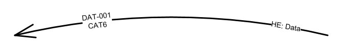
There is text displayed at each end of the wire. On the "Start Terminal" end of the wire, the Wire Component ID, Model Number and Head End are displayed. The default setting is to have these merged but they can be unmerged by changing the Merge Text block setting in the Shape Data Window or right-click options. These text fields can be moved anywhere around the main wire shape by using the yellow control handle(s).
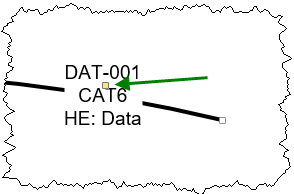
Bulk Wire 2
This Shape looks like this when dropped on a Visio page:
On the "Start Terminal" end of the wire, the Wire Component ID, Model Number, and Head End display. The default setting is to have these merged but they can be unmerged by changing the Merge Text block setting in the Shape Data Window or right-click options.
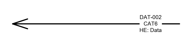
Bulk Wire 3
This Shape looks like this when dropped on a Visio page:
On the "End Terminal" end of the wire, the Wire Component ID, Model Number, and Head End display. This Bulk Wire Shape is slightly different from the other two in that the "plain" end of the wire is the "End Terminal" end vs. the arrow on the other Bulk Wire Shapes.
Finish Wire
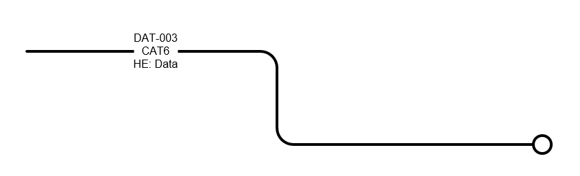
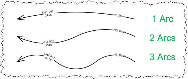
There is one Finish Wire shape and it is intended to be used on Schematic and Line pages in Visio. This Shape looks like this when dropped on a Visio page, depending on your settings:
By default, the Wire Component ID displays on each end of the shape. This can easily be changed in the Show Text settings in the Shape Data Window or right-click menu options to show the Component ID, Model, or Terminal information.
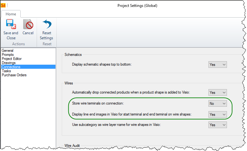
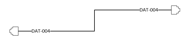
The Wire Shape may look different than the image above if you have set the Start Terminal and End Terminal field for the wire on the Specifications tab and have the "Display line end images in Visio for start terminal and end terminal on wire shapes" Project Setting set to "Yes":
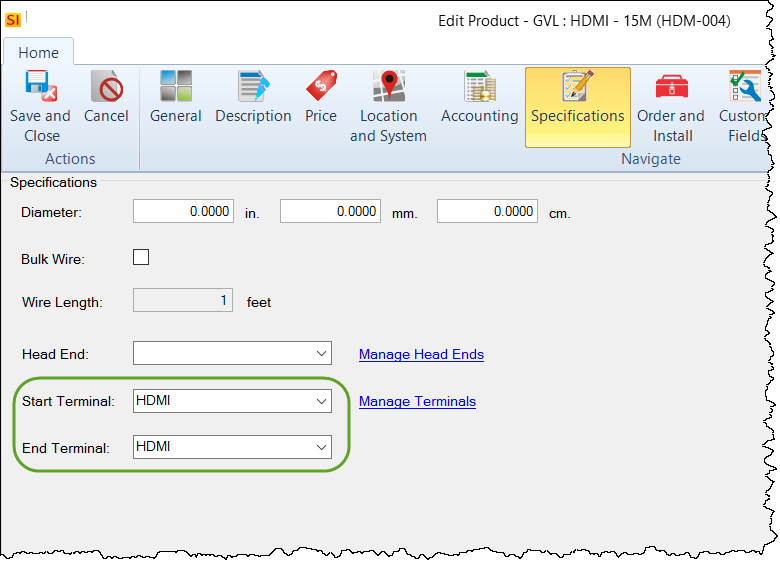
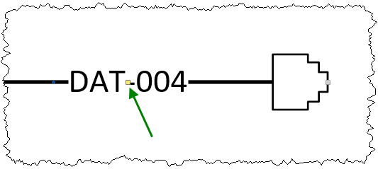
In this example, both the Start and End Terminal fields were set to "RJ45" and the Finish Wire Shape will look similar to this:
Below is an image showing all of the available line end images:
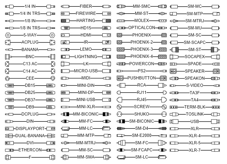
If you want to create your own line end images, click here for instructions.
The other Project Setting shown above, "Store wire terminals on connection", when set to "TRUE", will automatically fill in the Start Terminal and End Terminal fields when the wire is connected to Schematic Shapes.
Line Connector
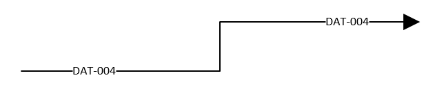
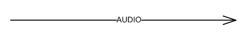
The Line Connector shape is not linked to any Products by default. This shape is intended to be used on Line pages in Visio where you just want to show what connects to what, without actually dropping specific wires on the page. This Shape looks like this when dropped on a Visio page:
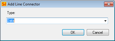
Unlike the other Wire Shapes, when the Line Connector is dragged from the Stencil to a Visio page, you will not be prompted to select a Wire from your Catalog to add to the Project. Instead you will be prompted to select from your list of Subcategories associated with your Wire and Cable Category. Whatever you choose will display on the Shape:
Shape Data Window
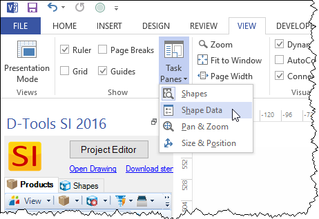
All user adjustments are accessed through the Shape Data window. To display the Shape Data window, click the View tab then select "Shape Data" from the Task Panes dropdown:
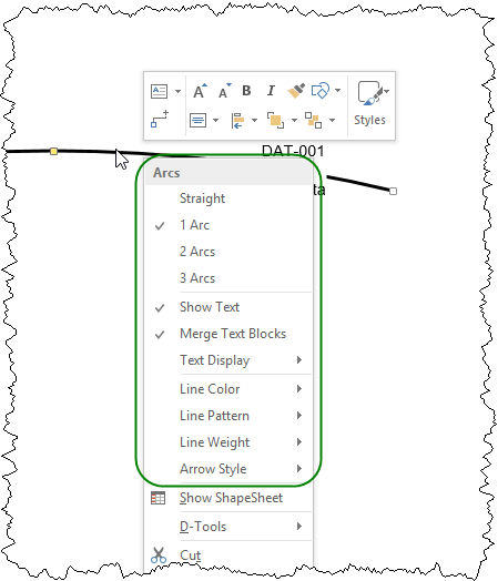
The most common used settings can also be accessed by right-clicking the Shape:
Bulk Wire Shape Data
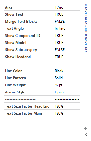
Arcs: Default is one arc. Here you can change the shape to have one, two, or three arcs.
Show Text: Default = TRUE.This will show or hide the text blocks for the shape.
Merge Text Blocks: Default = FALSE. You can merge the Wire Component ID, Model Number, and Head End into one text block when set to TRUE.
Text Angle: Default = In-line. This means the text will stay in-line with the wire shape. The other option is "Level".
Show Component ID: Default = TRUE. This will allow you to Show/Hide the Component ID on the shape
Show Model: Default = TRUE. This will allow you to Show/Hide the model information on the shape.
Show Subcategory: Default = FALSE. This will allow you to Show/Hide the Subcategory of the product on the shape.
Show Headend: Default = TRUE. This will allow you to Show/Hide the Headend information on the shape.
Line Color: Default = Black. You can change the line color.
Line Pattern: Default = Solid. You can change the line pattern.
Line Weight: Default = 3/4 pt. You can change the line weight.
Arrow Style: You can change the arrow style on the wire. Default varies between the Bulk Wire Shapes.
Text Size Factor Head End: Default = 120%. Allows you to change the text size on the Headend text section independent of the main text section when Merge Text is set to FALSE.
Text Size Factor Main: Default = 120%. Allows you to change the text size main text independent of the Headend text section when Merge Text is set to FALSE.
Finish Wire Shape Data
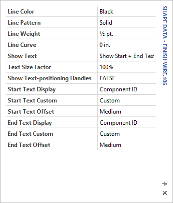
Line Color: Default = Black. You can change the line color.
Line Pattern: Default = Solid. You can change the line pattern
Line Weight: Default = 1/2 pt. You can change the line weight.
Line Curve: Default = 0 in. You can change the line curve of the wire from a right angle to a rounded curve.
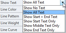
Show Text: Default = Show Start + End Text. There are multiple options for how and where the Wire Component ID (or custom text) displays on the Finish Wire shape.
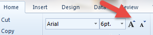
Text Size Factor: Allows you to change the text size of the Start and End text relative to the Middle text so you can have different text sizes for the ends vs the middle. To change the middle text size you can use the Visio menu Text larger/smaller function.
Show Text-positioning Handles: Default = FALSE. Setting this to TRUE will display a yellow handle next to the Start/End text on the wire which will allow you to move the text.
Start Text Display: Default = Component ID. You can choose which text you want to display on the start area of the shape. Choices are Component ID, Custom, Model, Terminal.
Start Text Custom: If you choose Custom from the Start Text Display option you can add custom text here.
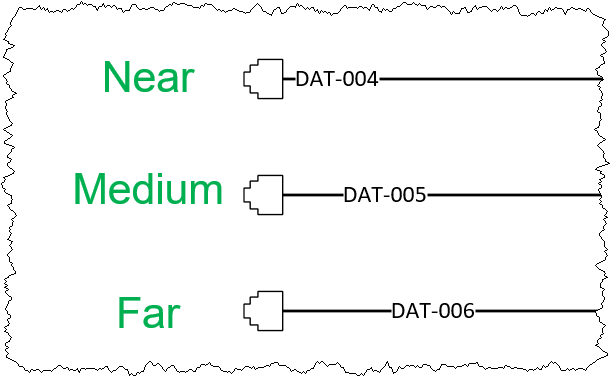
Start Text Offset: Default = Medium. This determines the default position of the Start text relative to the end of the wire shape. Choices are Near, Medium, and Far.
End Text Display: Same as Start Text Display but on the other end of the wire shape.
End Text Custom: Same as Start Text Custom but on the other end of the wire shape.
End Text Offset: Same as Start Text Offset but on the other end of the wire shape.
Line Connector Shape Data
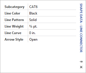
Subcategory: Here you can change the text that displays on the Line Connector Shape. This is a list of the Subcategories associated with your Wire and Cable Category.
Line Color: Default = Black.You can change the line color.
Line Pattern: Default = Solid.You can change the line pattern.
Line Weight: Default = 3/4 pt.You can change the line weight.
Line Curve: Default = 0 in. You can change the line curve of the connector shape.
Arrow Style: Default = Open. You can change the arrow style on the connector shape. Choices are Open, Filled, and Closed.
- © Copyright 2024 D-Tools