Plan Shapes
![]()
Details
There are many different shapes available for the "plan view" style drawing in Visio.
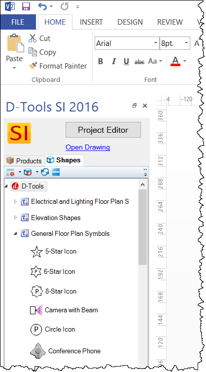
General Floor Plan Shapes
Plan Shapes are generally simple shapes intended to show placement of equipment from an overhead view, e.g. on top of a floor plan. They are located in the General Floor Plan Shapes Stencil:
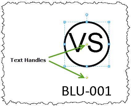
The text that is displayed in the icon shapes are based on the abbreviation of the Category of the Product. The text on the bottom is the unique Component ID of the Product. An example Plan Shape is shown below:

There are some General Plan Shapes that have unique properties, Dome Camera W/Coverage and Motion Detector W/Coverage:
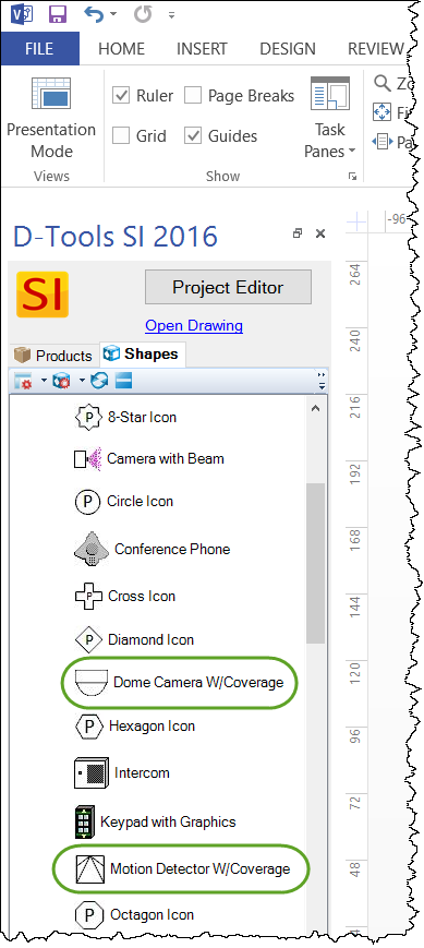
Click here for details.
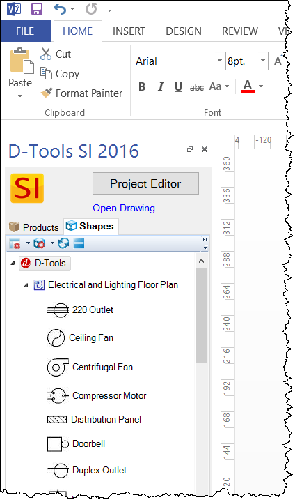
Electrical and Lighting Plan Shapes
The Electrical Plan Shapes stencil contains all of the shapes that could be used in documenting high voltage electrical and lighting projects. It contains a selection of lighting fixtures, electrical outlets, and electrical switch shapes.
 .
.
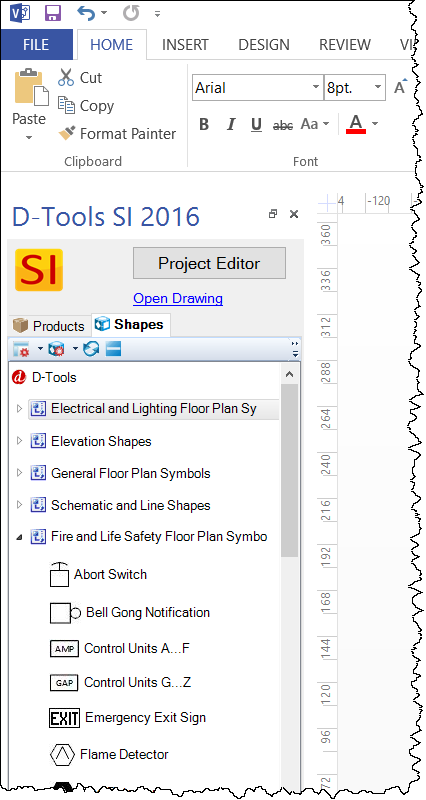
Fire and Life Safety Plan Shapes
The Fire and Life Safety Floor Plan Symbols stencil has a variety of shapes for representing fire and life safety systems.
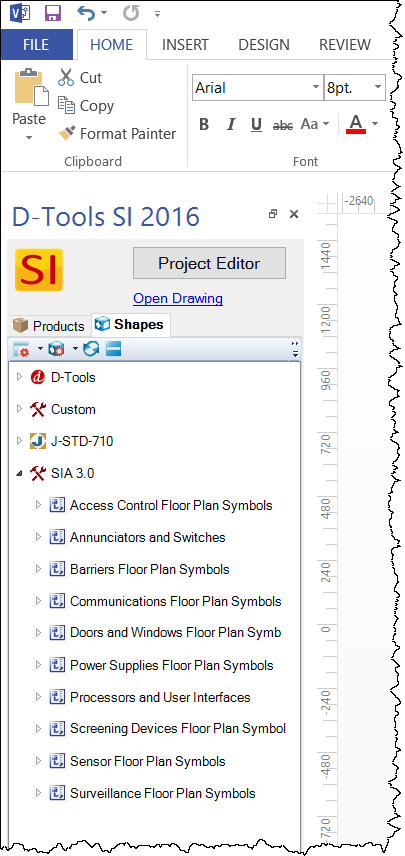
SIA 3.0
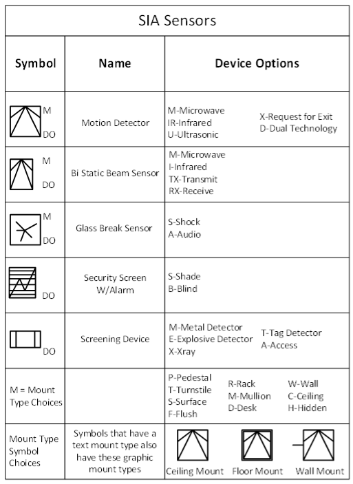
The SIA 3.0 stencil has shapes that were created based on the SIA Architectural Graphic Standard document. There are various categories of shapes available.
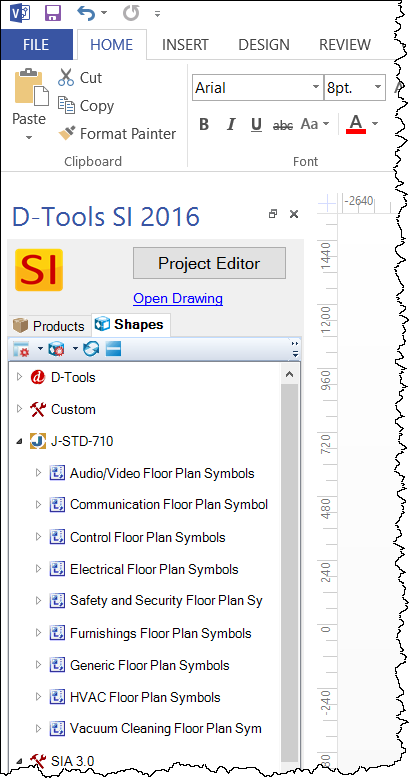
J-STD-710
The J-STD-710 stencils have shapes created based off of the J-STD-710 Drawing Symbols document. There are various categories of shapes available.
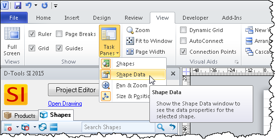
Shape Data Window
All user adjustments are accessed through the Shape Data window.
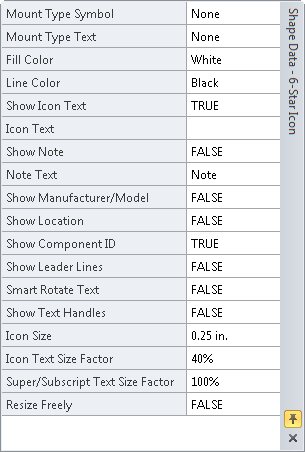
Regardless of the Plan shapes used, they all have similar properties in the Shape Data window. Some options may not be available on all Plan shapes.
Mount Type Symbol: There are three options:
- Ceiling Mount is the default and is just the plain icon shape of choice.
- Floor Mount is the icon shape of choice with a box surrounding the shape.
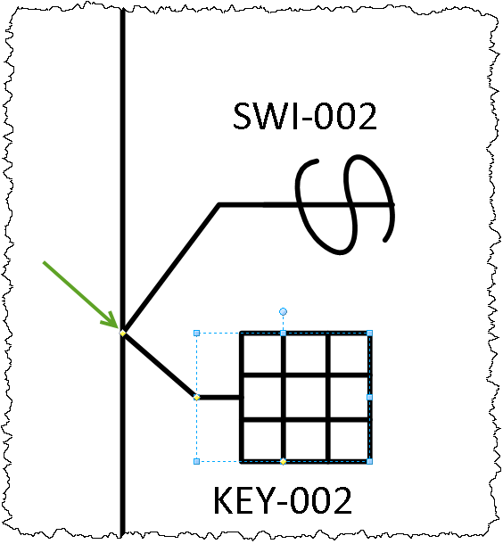
- Wall Mount is the icon shape of choice with a "T" shape handle off of the left side of the shape.

The Wall Mount option has a line extension feature that allows the user to connect multiple wall mount devices to the same location on a wall. For example if you wanted to locate a low voltage keypad next to a high voltage switch you would grab the yellow control handle at the end of the wall mount line and stretch to connect to the wall.
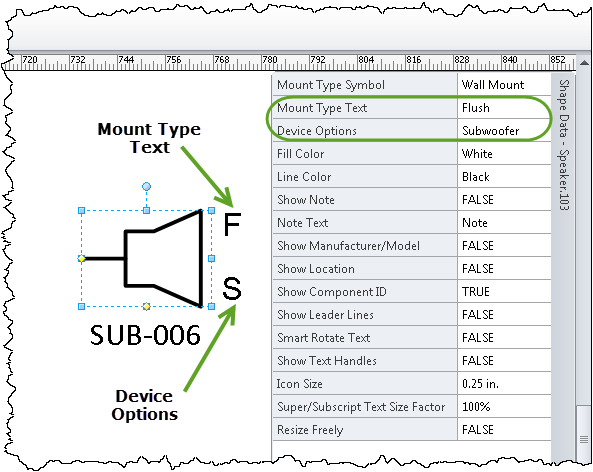
Mount Type Text: In addition to the Mount Type Symbols we also included Mount Type Text that puts a letter to abbreviate the mount type in the upper right section of the shape. All of the text mount types have been standardized to mean: P-Pedestal, T-Turnstile, S-Surface, F-Flush, R-Rack; M-Mullion, D-Desk, W-Wall, C-Ceiling, H-Hidden.
Device Options: Device Options display on the bottom right side of shapes. The list of available device options are specific to each shape. A complete list of device options for each shape can be found on the Symbol Legend shape in each stencil, see below. The specific device option choices came directly from industry standard documentation.
Fill Color: We implemented a new color schema for the plan shapes based on the "Rothian" color scale. The default is white. We also implemented a smart text functionality that evaluates the background color for brightness and will automatically change the internal text to black or white depending on the brightness level of the background color. In the example below, the white, orange, and green shapes have black text while the blue has white text.

Line Color: You can customize the Line Color with the same color scale as the fill colors. As you can see this can result in some interesting color combinations. The default line color is black.
Show Icon Text: The Icon text is usually three letters that abbreviate the Category of the product being placed on the drawing page. These abbreviations are defined by the user during the software setup. The default is CID (Category ID). In previous versions Sof D-Tools we relied on the CID to differentiate the symbols on a page. If there were two square symbols on the plan view one could be for lighting (LIT) and one could be used for CATV (CTV). Since our new crop of floor plan symbols are designed to be more specific the CID is not needed and these symbols usually have this feature hidden.
Icon Text: You can enter free form text in this field if you want the Category ID to display something else. This feature is hidden in the shapes that do not need it.
Show Note: If set to True you can add text to the Note field and it will show up in the note call out. You can use the yellow control handle to move this text around. Default is set to False.
Note Text: Any text you add here will end up on the note tag of the plan shape.
Show Manufacturer/Model: Set this field to true to display the specific manufacturer and model linked to the symbol. This field moves with the COMPID field. Default is false.
Show Location: Set this field to true to show the location of this specific symbol if set in the database. This field moves with the COMPID field. Default is false.
Show Component ID: True or False, default = TRUE. This will turn the Component ID field on or off. In addition you can use the yellow control handle to move the component ID around the shape as needed. This is useful when you rotate the shape.

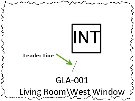
Show Leader Lines: When set to true, attachment (leader) lines display on the note and COMPID fields. The default is false,
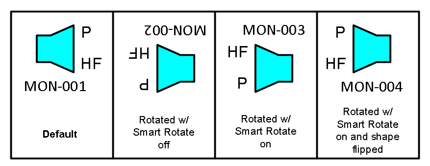
Smart Rotate Text: Shapes that are designed to attach to a wall often need to be rotated to match walls they are attached to. When rotated, the text may be upside down. When the Smart Rotate Text function is set to true you can manipulate the text so it is readable. In some cases you may need to use the Visio command: Home (tab)->Position->Rotate Shapes->Flip Horizontal to get the Mount Type Text and Device Options to display in their correct positions.
Show Text Handles: When set to true yellow control handles will appear on the CID, Mount Type and Device Option text fields. Click the appropriate handle to move around.
Icon Size: Use this field to adjust the overall size of the symbol while keeping the aspect ratio. For most symbols the default is set to .25 inches.
Icon Text Size Factor: If the shape has Icon Text visible you can use this field to adjust the size of the Icon Text. This is the Category abbreviation in most cases.
Super/Subscript Text Size Factor: Use this field to adjust the size of the text in the Mount Type and Device Option fields.
Resize Freely: Set this field to true if you want to resize the symbol to your own specifications. You can change size as well as aspect ratio.
Pre-assigned Categories/Subcategories
We pre-assigned categories and subcategories on the General Plan Shapes according to the table below using our new for SI2016 2013 Category Assignment process. These assignments can be easily modified.
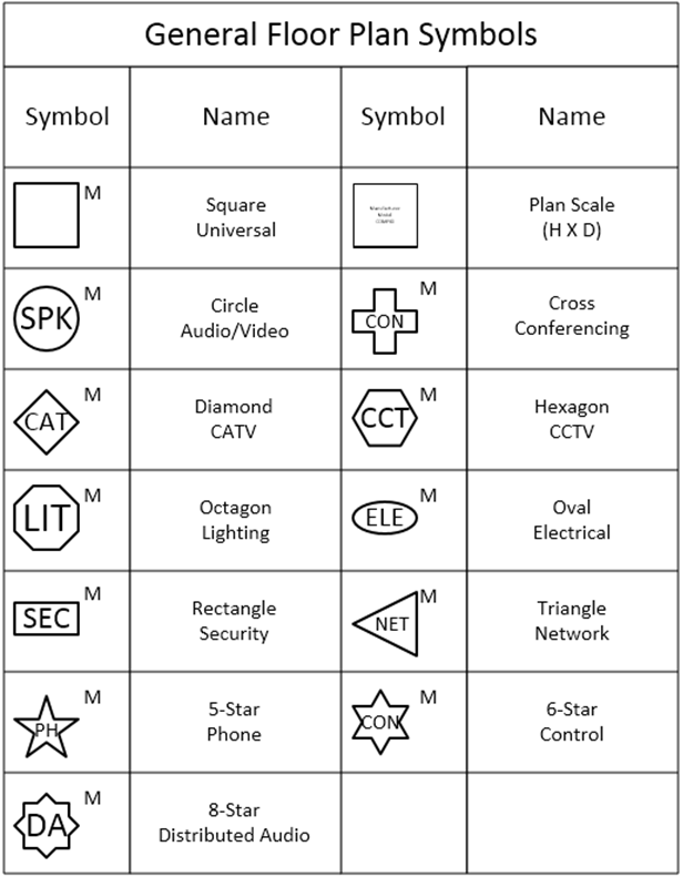
Symbol Legend Shapes
Each set of Plan shapes (stencil) has a shape named "Symbol Legend" that details what shapes are available in each stencil as well as what device options are available for each shape. These shapes were intended to be used on the Cover Sheet of our stock Visio Stencils to explain what each symbol represents on your Plan pages. An example Symbol Legend shape is shown below:
Click here to learn how to edit these Symbol Legend shapes.
- © Copyright 2024 D-Tools