Plan/Schematic Drawings
Plan and Schematic Drawings
Create Visio Plan Drawing
Meanwhile, Franz has been in communication with the architect, Irene Drawthings, who designed the MacGowan’s house. She does not want to provide the .dwg file since it is her intellectual property but would be happy to provide a printed copy of the plans. After explaining that they just want the two rooms that they working on, the architect agrees to give them a partial floor plan and an elevation in .dwg format. Franz sent Irene a handy .pdf file (that he downloaded from the D-Tools forum http://www.d-tools.us/showthread.php?t=1041 ) detailing the commands that must be run on the file in order to import into Visio. At first she did not want to spend the two minutes required to run these commands but a phone call from an angry Mrs. MacGowan helped.
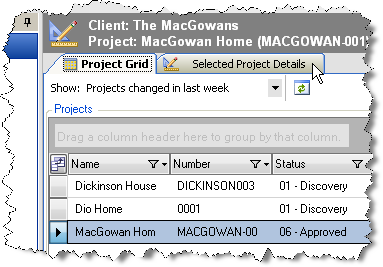
Once he receives the email with the .dwg files, he downloads them to his machine and renames them. Since these are not actual SI 5 project files, they do not name these files with the project number as they do for SI 5 project files. To keep all files together he launches SI 5 and then clicks the Projects tab. He selects the project in the Project Grid and then clicks the Selected Project Details tab:
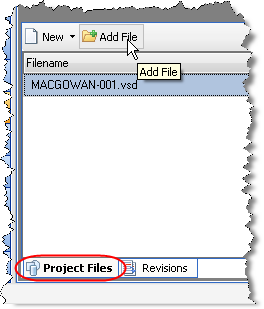
He then clicks the [Add File] button:
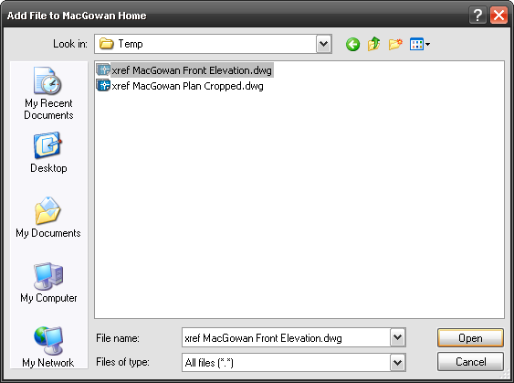
The Add File form opens and he browses to the file and then clicks [Open]:
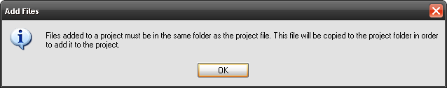
He clicks [OK] for the message stating that the files will be copied to the same directory as the project file:
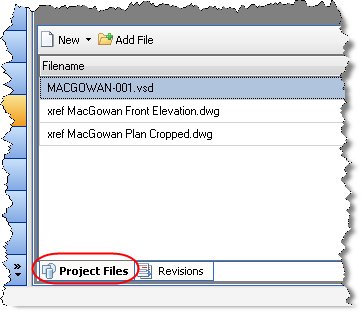
The files that he added are now displayed in the “Projects files for:” section:
While he is in SI 5, he also changes the status of the Project to “Engineering” and lets Laura know that it is her time to shine.
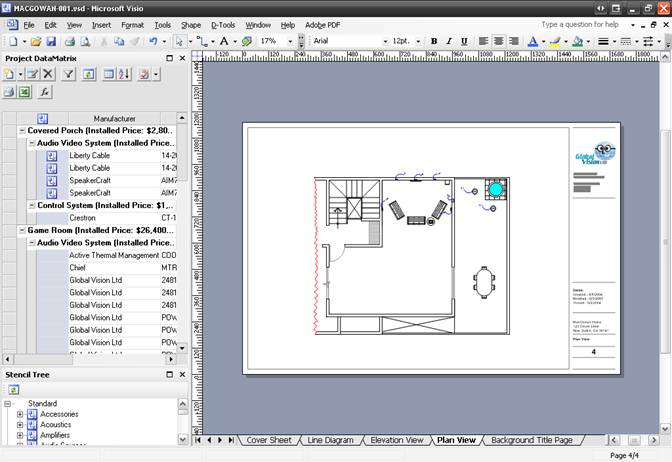
Laura then opens the Visio file for the Project and clicks the Plan View tab. Her first order of business is to insert the AutoCAD file onto a Plan page type in Visio. Laura is kind of a geek and actually read the user’s guide for SI 5 and she follows the instructions for this (see Visio Interface section of the SI 5 User’s guide for details).
She begins by dragging out some stock Visio shapes to represent the furniture in the house (Laura uses Visio 2003 Professional so she has access to many stock Visio shapes):
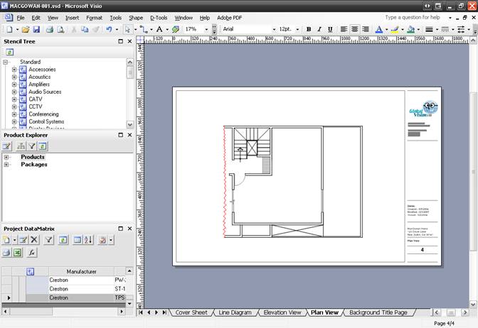
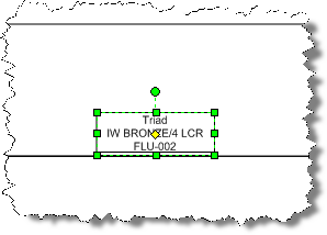
She then drags out one of the front speakers for the surround system. The default Plan shape for a speaker drops:

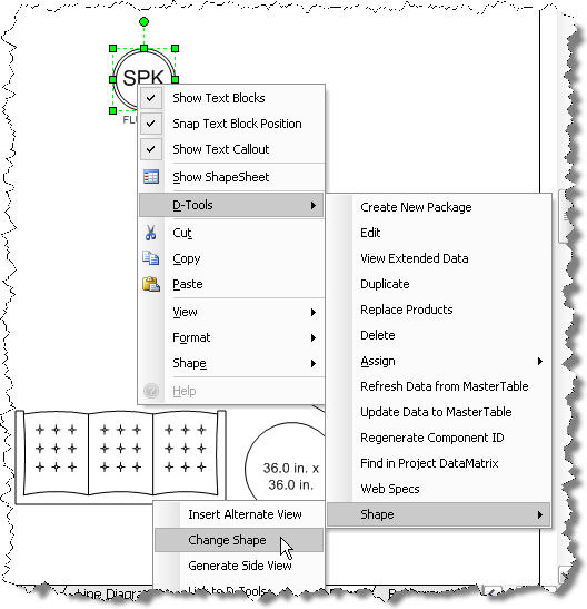
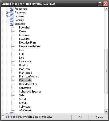
For the in-wall and on-wall speakers in projects, she prefers to show a scaled shape instead of the default Plan speaker shape. To change the shape, she right-clicks the shape and selects D-Tools->Shape->Change Shape:
She selects the “Plan Scale” shape and clicks [OK]:
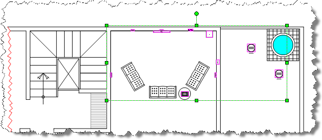
The shape is then changed to a scaled shape that she then positions in the wall of the drawing:
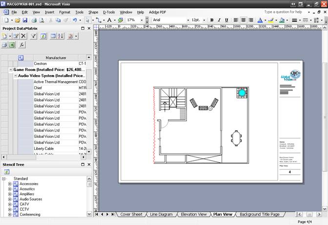
She continues adding all of the speakers to the page. For the in-ceiling speakers on the porch she leaves the default Plan shape. She then adds the touch panel, plasma, and the rack to the page (all products are selected below to make them easier to see):
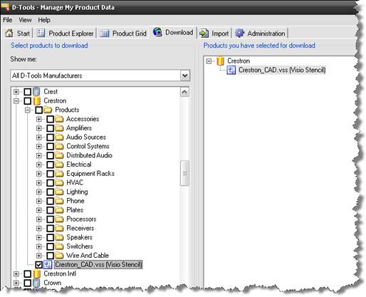
The touch panel is a specific Manufacturer shape rather than the stock generic shapes in SI 5. When GLV downloaded their Crestron data from D-Tools, they chose to download the Manufacturer specific Visio stencil as well:
The next products that she drags over to the page are the wires for the products. She then connects the wires to the shapes. When the green connection point turns red, the shapes are connected:
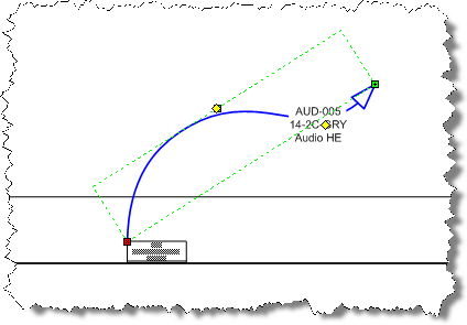
When finished, the page looks like this:
When she finishes, she saves and closes the Project.
AutoCAD Schematic Drawing
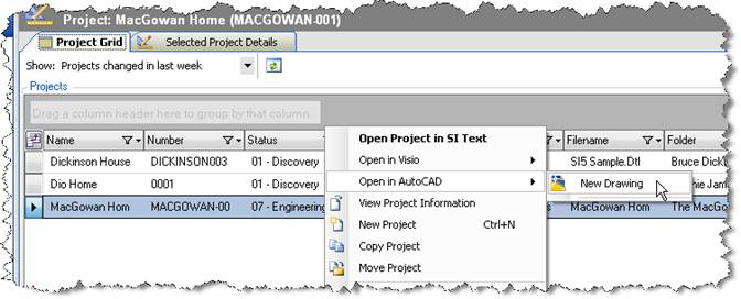
She is going to create a Schematic drawing for the system but wants to use AutoCAD for this. She selects the Project in the Project Grid and then right-clicks and selects Open in AutoCAD->New Drawing:
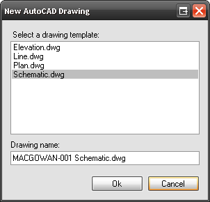
She is then prompted to pick a drawing template. She selects the Schematic.dwg template, types in a file name, and clicks [OK]:
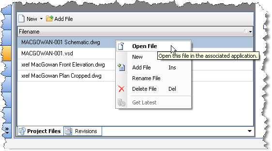
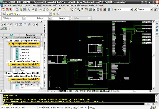
The file was added to the Project Files list. She then selects the file right-clicks and selects Open File:
The Project launches in AutoCAD:
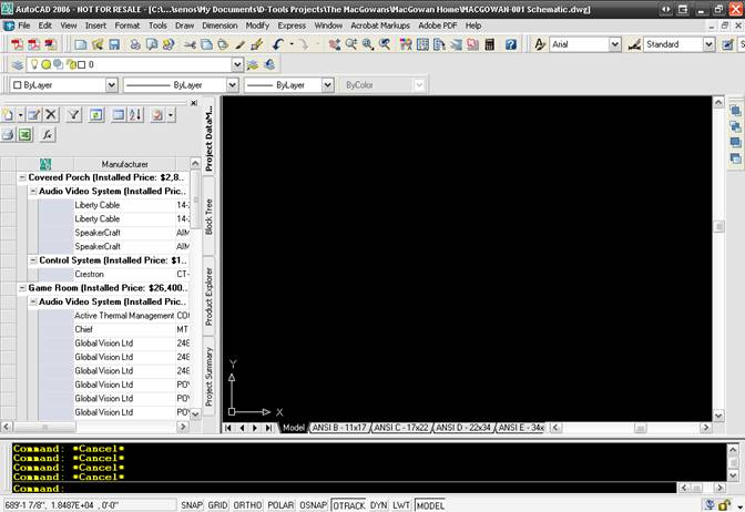
![]() The display settings above are based on my personal settings. Your AutoCAD interface may vary slightly depending on your settings.
The display settings above are based on my personal settings. Your AutoCAD interface may vary slightly depending on your settings.
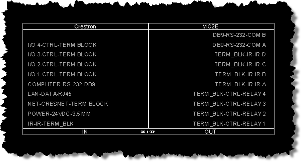
She begins by dragging out the all of the products that she wishes to wire. ![]() The Schematic blocks in SI 5 list the inputs on the left side of the block and the outputs on the right side of the block. Each I/O has a connection point next to it:
The Schematic blocks in SI 5 list the inputs on the left side of the block and the outputs on the right side of the block. Each I/O has a connection point next to it:
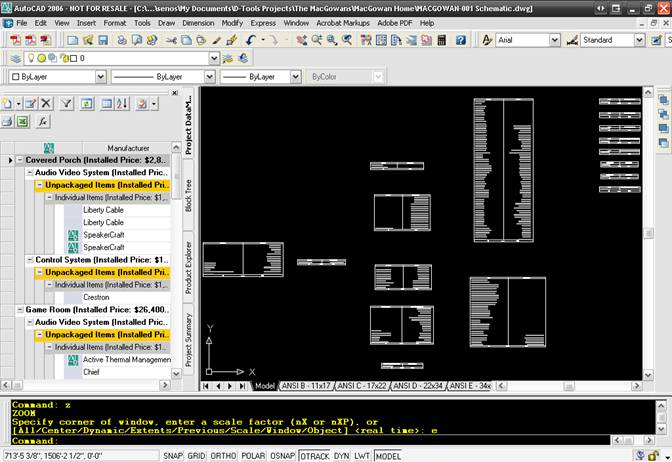
She moves and positions the blocks on the sheet until they are in the desired positions:
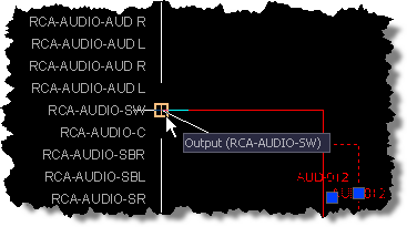
She then drags out the wire blocks. The wire blocks used on Schematic sheets in SI 5 are red when not connected to I/Os, and turn green when both ends are connected to I/Os:

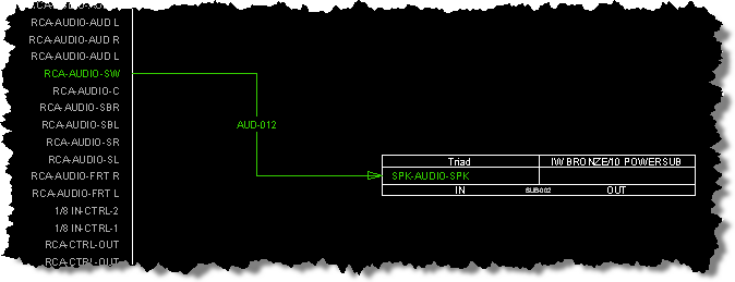
When you move and end of the wire block to an I/O connection point, an orange box displays:
When she is finished making connections, the drawing looks like this:
- © Copyright 2024 D-Tools