Elevation Drawing
Table of contents
How to Create an Elevation Drawing
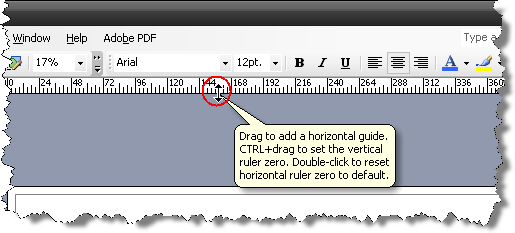
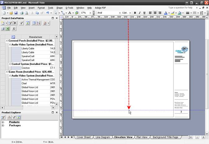
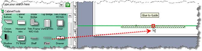
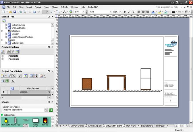
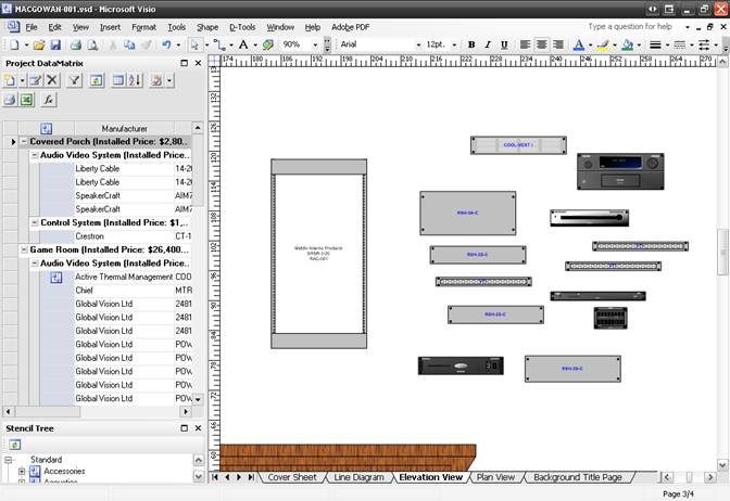
Laura then begins work on an Elevation view by clicking the Elevation tab. This system will be incorporated around an existing fireplace that houses a fish tank filled with many species of fish including a killer crayfish. How a crayfish lives in a saltwater tank is a mystery to scientists. Fortunately Franz took photos of the room while he was at the MacGowan’s house so she has a basis for the drawing. She begins this drawing by dragging a guideline down from the ruler to the page to help line up shapes. To do this, left-click and drag when the cursor turns into a double arrow:
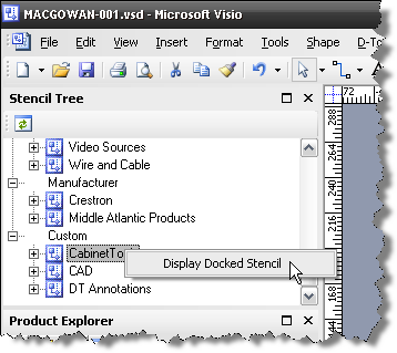
She then right-clicks the Cabinet Tools stencil in the Stencil Tree and selects “Display Docked Stencil”.
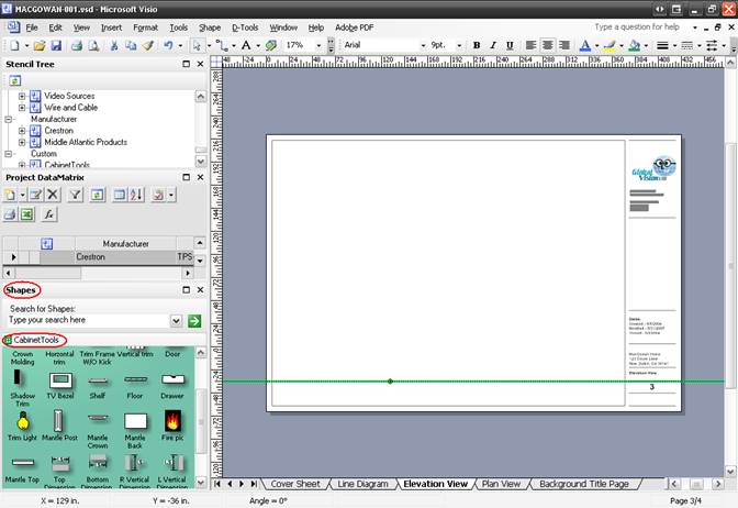
The shapes in the Cabinet Tools stencil are displayed in the Shapes window:
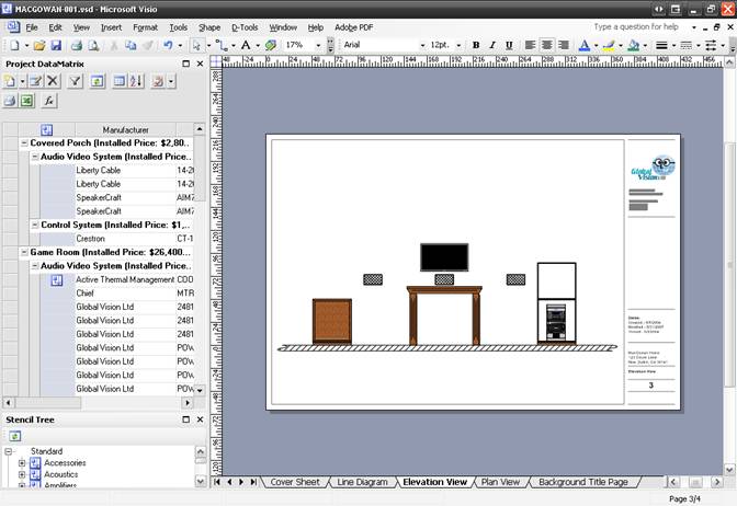
She then drags the Floor shape from the stencil to the drawing page:
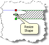
The Floor shape is resized using the handles on either end of the shape:
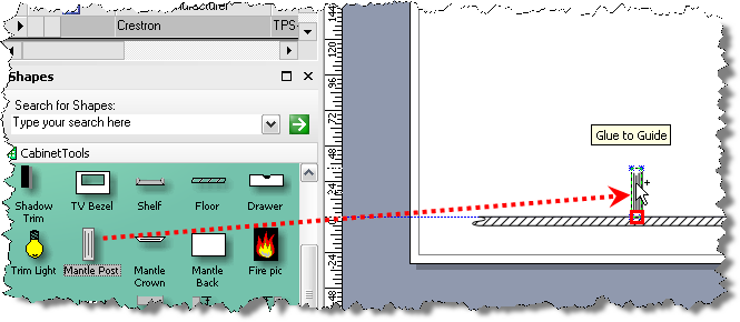
The next things that she lays out are the fireplace and existing cabinetry in the room. She begins by dragging out the Mantle Post shape to the page:
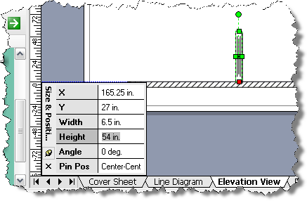
To make sure that the mantle is the proper size, she selects View->Size & Position Window:
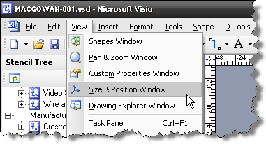
With the shape selected, she then enters in the proper height in the “Height” field of the Size & Position Window:
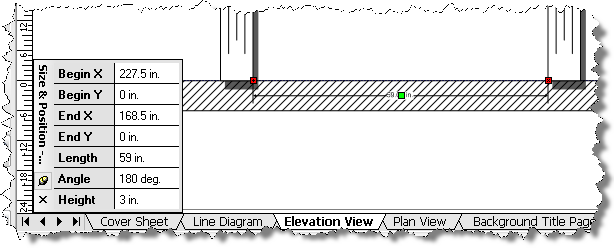
She then copies and pastes the shape to represent the other side of the mantle. To assure a proper distance between the mantle posts she drags the Bottom Dimension shape to the page. She types in the dimension in the Size & Position Window and snaps the Bottom Dimension shape to one Mantle Post shape then moves the second Mantle Post into position:
Once positioned correctly, she deletes the Bottom Dimension shape from the page. She continues to drag shapes form the Cabinet Tools stencil to complete the fireplace and cabinets:
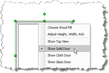
She keeps the cabinet bottom on the right open to show where the rack will go and adds a door to the cabinet on the left by right-clicking the shape and selecting “Show Solid Door”:
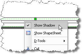
To remove the shadow from a shape, right-click and uncheck “Show Shadow”:
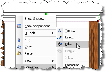
To fill in the color for the cabinets, she selects each shape then right-clicks and selects Format->Fill:
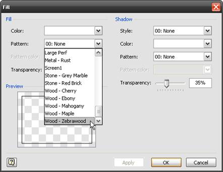
She then selects “Wood – Zebrawood” from the “Pattern” dropdown:
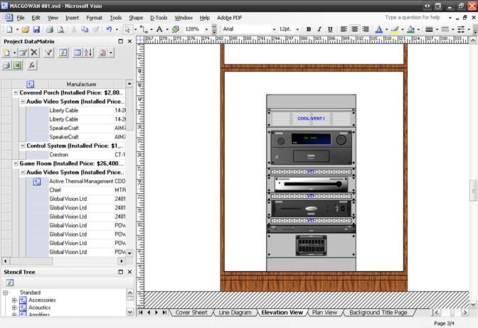
She then begins work on building the rack. She begins by dragging over the rack and rack components from the PDM to the drawing page:
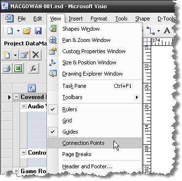
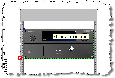
She begins assembling the rack by first positioning the electronics. Each elevation shape has a connection point for snapping to the connection points on the rack which are spaced out at 1.75” intervals. To see the connection points she selects View->Connection Points:
A red box indicates when two connection points are connected:
She continues positioning the electronic components including the vent at the top of the rack:
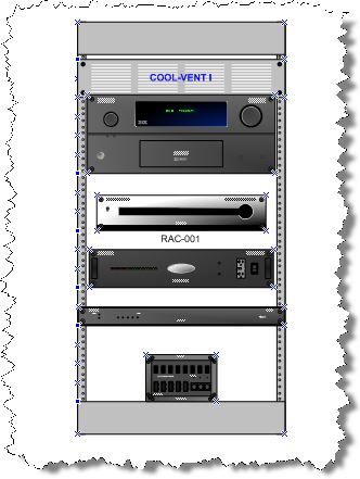
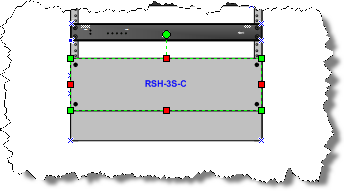
Next she drags over the rack shelves and positions them around the components. When a shape covers another shape, she uses the Visio “Bring to Front” and “Send to Back” commands. Clicking once selects the foreground shape:
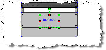
She pauses then clicks in the center of the shape to select the shape behind the shelf:
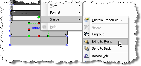
She then right-clicks and selects Shape->Bring to Front:
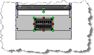
When finished, she selects all of the rack shapes and moves them to the cabinet shape:
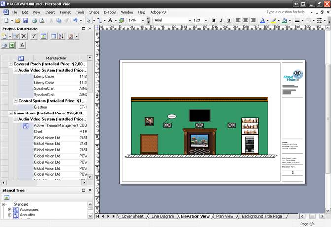
She then drags over the plasma and front speakers and positions them:
The final touches are added to the drawing. She uses the Insert->Picture->From file… command to add some images to personalize the drawing for the client:
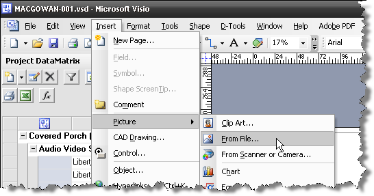
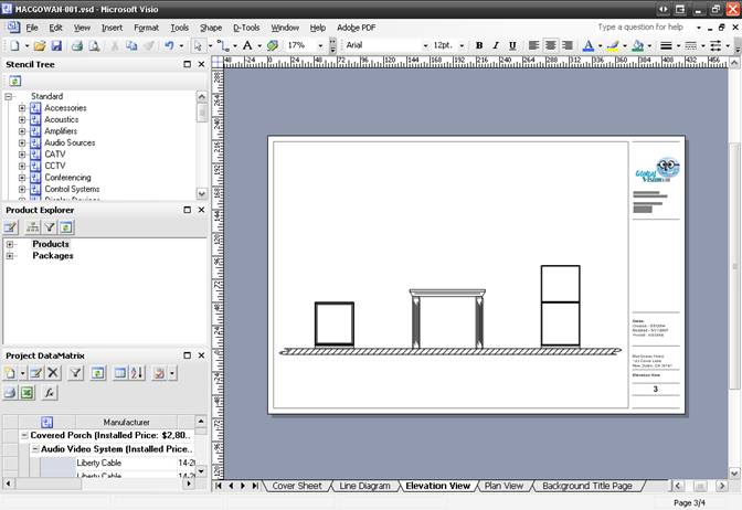
When finished, the elevation drawing looks like this:
Laura then saves, closes, and Checks in the project.
More Information
- © Copyright 2024 D-Tools