Wire Auditing
Table of contents
Wire Auditing in SI 5
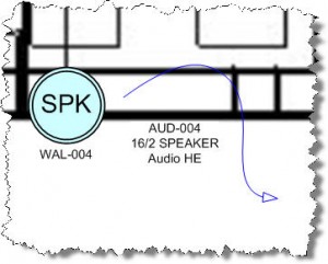
There has been a change in the way wire behaves in System Integrator when working within Visio. Each end of our wire shapes are now treated uniquely: one is the “From” or “Source” end and the one with the arrowhead is the “To” or “Destination” end. This was not the case until the release of 5.2 when more control was added to the wire auditing function within SI. I noticed this when I opened the project I created last year for CEDIA and some of my wires on the Plan page were not connected anymore.

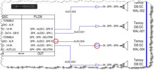
The reason this wire is now disconnected is that I have these two devices drawn and connected on a Schematic page in the project as well and the “Source” end of the wire is connected to an amp while the “Destination” end is connected to the speaker:
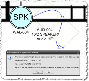
Now when I try to reconnect the wire to the speaker on the Plan page, I get the following message:
If you choose [Yes], the wire will disconnect on the Schematic page. If you choose [No], the wire will not connect on the Plan page. The reason for this is that on the Schematic page, the “Destination” end of the wire is attached to the speaker and on the Plan page I am trying to attach the “Source” end of the wire to the same speaker. There a few things you can do to get this wire to connect on the Plan page, the method you choose is up to you.
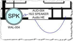
You could simply connect the “Destination” end of the wire on the Plan page. The software will accept this connection:
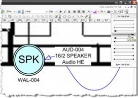
If you don’t like the way that looks, then you can change on which end the arrowhead displays. You can do this on per case basis by using the Line Ends command:
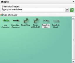
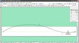
The best thing to do is to go modify the Rough-In wire shapes within the stencil so that you don’t have to this on a per wire drop basis. To do this, open the Wire and Cable stencil for edit and double-click one of the Rough-In wire shapes to open in “edit mode”:
Select the shape (green dashed outline) and change the Line Ends. Then save the shape and save the stencil.
Repeat this for the other Rough-In shape if desired. For more details on how to edit stencils/shapes, see this post Modifying Existing SI 5 Shapes.
- © Copyright 2024 D-Tools

