Display Custom Properties
How to Display Custom Properties on D-Tools Visio Shapes
Let us say you want to display a custom property like the value in “Custom Property1” on an SI5.5 Visio shape or you want to display the “Location” or “Zone” on a D-Tools Visio shape. This is now possible with the System Integrator 5.5 Service Pack 1 (SP1).
Note :- Not applicable for Schematic shapes.
Each Visio shape has a ShapeSheet which holds the data behind the shape. The ShapeSheet has many sections one of which is called “Shape Data”. SI5.5 looks for specific cells in this “Shape Data” section of the ShapeSheet and populates these cells with product data from the project file. For example if SI5.5 find(s) the cell “Category” in the “Shape Data” section of the ShapeSheet it will populate this cell with the “Category” for the product within the project file. SI5.5 will NOT create these cells in the ShapeSheet automatically– these cells must be added to the ShapeSheet and if they exist they will be populated from the project data file.
This is the list of cells which can be populated from the SI5.5 project file once you add them to the ShapeSheet (the ones in bold are usually part of most of the existing SI5.5 shapes):
| Property Name |
| ComponentID |
| Manufacturer |
| Model |
| Type |
| Category |
| Height |
| Width |
| Depth |
| CustomProperty1 |
| CustomProperty2 |
| CustomProperty3 |
| CustomProperty4 |
| CustomProperty5 |
| CustomProperty6 |
| CustomProperty7 |
| CustomProperty8 |
| CustomProperty9 |
| CustomProperty10 |
| SKU |
| Keyword1 |
| Keyword2 |
| Keyword3 |
| UnitCost |
| UnitPrice |
| UnitLaborHrs |
| ProductDescription |
| InstallPrice |
| Voltage |
| Amps |
| BTU |
| Hyperlink |
| IPAddress |
| SerialNumber |
| ClientDescription |
| Location |
| Zone |
| MSRP |
| Phase |
| Weight |
How to add a field in the ShapeSheet
1. Open Microsoft Visio 2007 (these instructions are for Visio 2007 only)
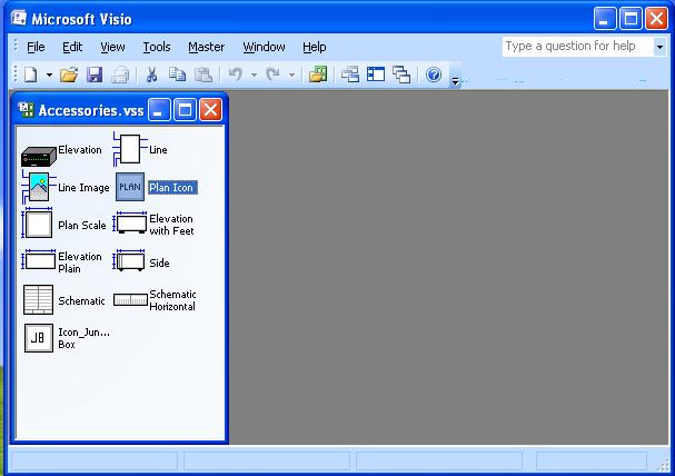
2. Open the stencil file via the File->Open command in Visio (do not double click the stencil from Windows Explorer as that will open stencil read only). The screen shot below shows the Accessories.vss stencil file opened.
Note: The default folder for SI5.5 stencils is “C:\Documents and Settings\All Users \Application Data\D-Tools\SI5\Visualizations\Stencils” for Windows XP and “C:\ProgramData\D-Tools\SI5\Visualizations\Stencils” for Vista.
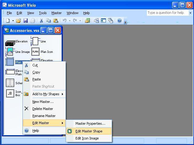
3. Open the master shape for editing. To edit a master either double-click the master shape (or) right click the shape and click ‘Edit Master ->Edit Master Shape’.
Note: Before editing a shape, it is advisable that you make a backup of the existing shape in the event that you make a mistake. To make a backup of the shape prior to opening for edit you can simply Copy and Paste the shape directly in the stencil.
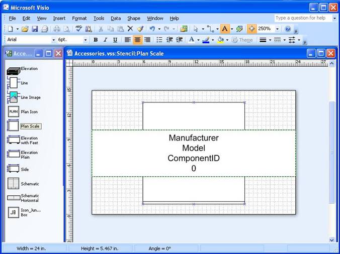
4. Open the ShapeSheet for the master shape. First select the main shape (when selected, the shape will have a dashed green border around it) and then select Window -> Show ShapeSheet from the main menu to open the ShapeSheet.
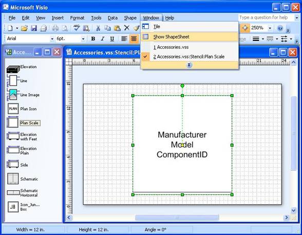
The ShapeSheet will open in a new window as shown below.
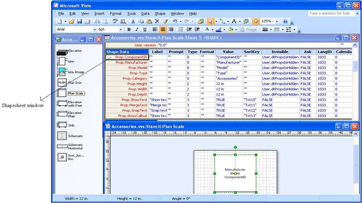
5. A ShapeSheet has many sections. Scroll to the “Shape Data” section of the ShapeSheet. Add a new row to this section. To add a new row select any row, right click and select ‘Insert Row’.
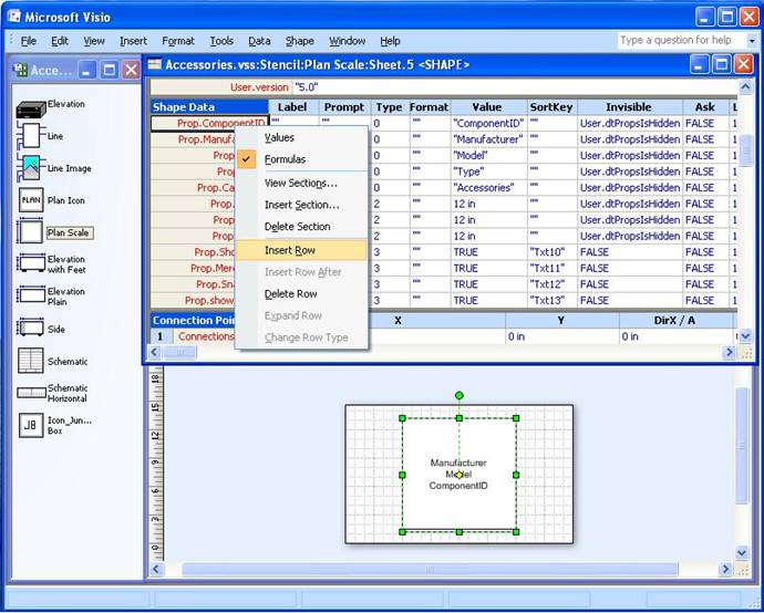
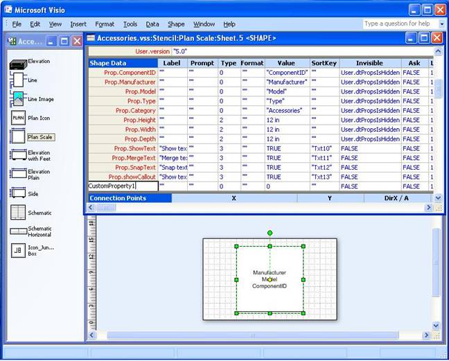
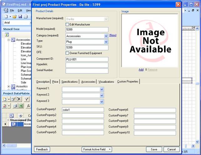
6. In the first column of the new row enter the property name. In this example we will type in “CustomProperty1” (without the quotes) as shown below since we want to show the Custom Property1 from the D-Tools data here.
How to display the custom property in a D-tools Shape
After you insert a new row called “CustomProperty1” we need to add this field to the shape text. Once we add this row to the shape text, the value in this row will display on the shape. This is how we see the ComponentID, Category, Manufacturer etc on the majority of SI5.5 shapes.
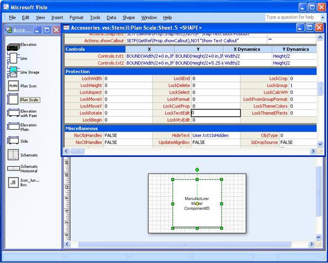
1. Unprotect the shape text so that we can add edit the shape text. To unprotect the shape text scroll to the “Protection” section in the ShapeSheet and change the value of LockTextEdit from 1 to 0 as shown below. Once we do this we can edit the text on the shape.
Note: If the LockTextEdit is 1 then the shape text is protected and cannot be changed.
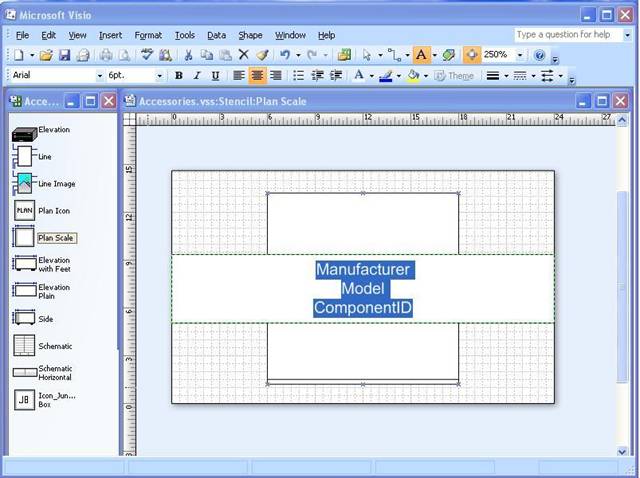
2. Select the master shape and click the “Text Tool” to edit the shape text (The text tool is present in the Standard toolbar and is displayed with the symbol “A”).
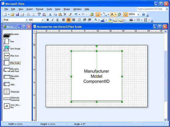
3. Once you click the “Text Tool” all text in the shape is selected and we can edit the text as shown below.
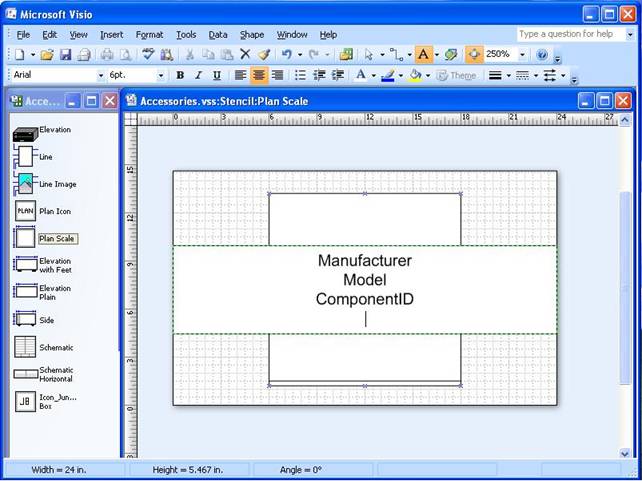
4. To add some new text to the shape click at the end of the text and press ‘Enter’. This leaves the existing text as it is and allows you to add new text.
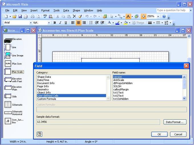
5. Select Insert->Field from the main menu. The Field dialog opens as shown below where user can insert or change fields.
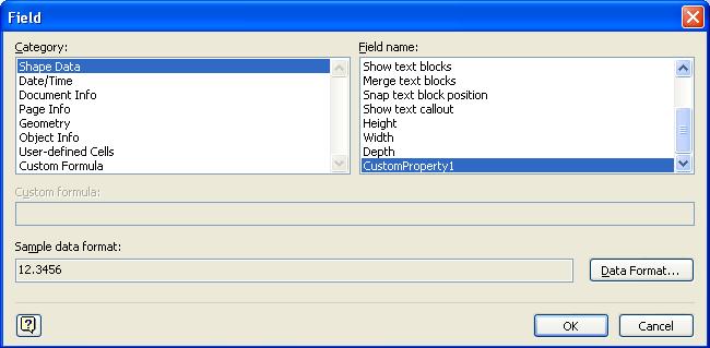
6. Click on “Shape Data” in the Category box (this will display all properties from the Shape Data section of the ShapeSheet). Scroll down in the Field Name box to see the new Property “CustomProperty1” which you just added as shown below.
7. Select the property and click OK to display this property in the text. This property will be shown as “0” (as shown below) as the value field for the property is blank in the ShapeSheet. Click outside the shape text to end the shape text edit.
8. On the ShapeSheet change the value of LockTextEdit (in the protection section) back to 1 so that the text fields can be protected from editing. This will prevent users from changing text in the shapes once added to a project.
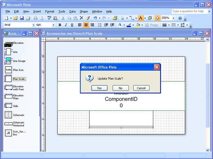
9. Close the ShapeSheet. Close the master shape. When the master shape is closed, Visio dialog prompts the user to save (as shown below). Click ‘Yes’ to update the master shape.
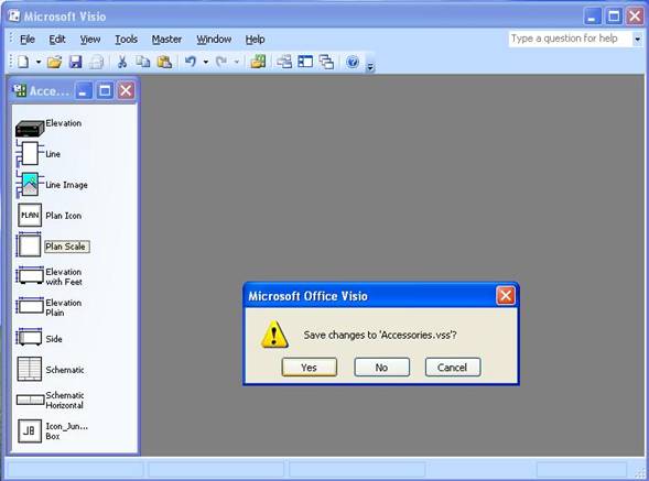
10. Close the stencil file. The Visio dialog prompts to save the file. Click ‘Yes’ to save the changes as shown in the figure.
11. Open a D-Tools Visio drawing from Navigator. Open Stencil tree( D-Tools | View | Display Stencil Tree) and select the master shape you just updated. In this example we selected the “Plan Scale” shape from the Accessories stencil. Drop this shape tp the drawing. This will open the “Add Product” dialog. Add a product. The shape will display the “CustomProperty1″ from the product date in the project file as shown below.
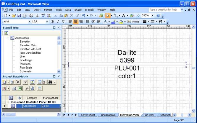
12. If your product has no value in CustomProperty1 – edit the product and type a CustomProperty1 and it will appear on shape.
- © Copyright 2024 D-Tools