Home > SI5 Documentation > User Guide > Visio Interface > Tips Tricks > Change Wire Color
Change Wire Color
Change Wire Color
Table of contents
Change Wire Color in Visio
D-Tools wires in Visio get a color based on the type – Audio wires show up as blue, Video as Red etc. You can customize the colors for the wire types by changing a formulae.
To change the wire color you need to modify the master shapes in the “Wire and Cable” stencil: –
- Open “Wire and Cable.vss” stencil in Visio by clicking File | Open and change File Type to Stencil. (File location – C:\Documents and Settings\All Users\Application Data\D-Tools\SI5\Visualizations\Stencils folder)
- There are 6 master shapes in this stencil – Line connector, Black Line connector, Finish Wire, Finish W/Mode + ID, Rough -In Wire, Rough-In Wire 2. User can change the Line color of all the master shapes except Black Line connector.
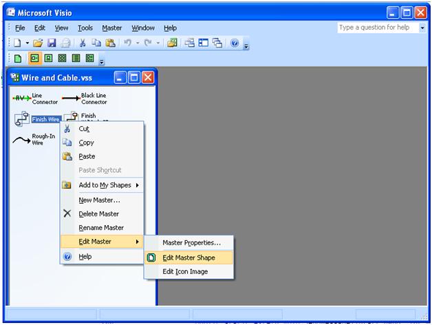
- Edit the master shape for which you want to change the color. To edit a master shape Right click shape and select Edit Master | Edit Master Shape or double click the shape. This master shape will be displayed in a new drawing window and can be edited.
- Select the wire shape in the drawing window and open the Shapesheet (Click Window | Show Shapesheet in the toolbar).
- The Shapesheet will open in new window. There are various sections in the Shapesheet. The line color is defined in User.LineColor row in the User-defined cells section.
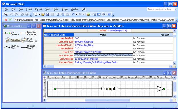
- This is the default formulae for the Line Color in the Finish Wire
=IF(LOOKUP(Prop.Type,”video”)=0,2,IF(LOOKUP(Prop.Type,”audio”)=0,4,IF(LOOKUP(Prop.Type,”control”)=0,20,IF(LOOKUP(Prop.Type,”phone”)=0,6,IF(LOOKUP(Prop.Type,”data”)=0,12,IF(LOOKUP(Prop.Type,”rgb”)=0,3,IF(LOOKUP(Prop.Type,”rf”)=0,5,0)))))))
Color codes are shown in bold text. The color codes determines the color of the wire. For e.g. according to the above formula ‘video’ type wire will be shown in red color (red = 2) and audio type wire will be shown in blue color (blue = 4). - You can see the default color codes in the Color Palette dialog (Open the Color Palette dialog from Tools | Color Palette)
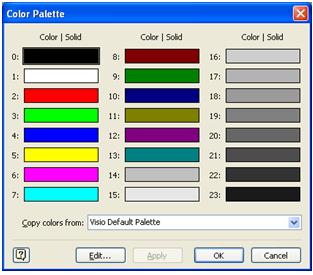
The color code 0 is for Black, 1 for White, 2 for Red etc. User can change the color code values in the formula to show different color wires. For e.g. to display the video wire in yellow and audio wire in green the line color formula will be
=IF(LOOKUP(Prop.Type,”video”)=0,5,IF(LOOKUP(Prop.Type,”audio”)=0,9,IF(LOOKUP(Prop.Type,”control”)=0,20,IF(LOOKUP(Prop.Type,”phone”)=0,6,IF(LOOKUP(Prop.Type,”data”)=0,12,IF(LOOKUP(Prop.Type,”rgb”)=0,3,IF(LOOKUP(Prop.Type,”rf”)=0,5,0))))))) - After changing the formulaes, close the Shapesheet window and the master shape drawing window (where you are editing the master). Save the changes to the master. Close the Wire and Cable stencil and save the changes to the stencil.
- © Copyright 2024 D-Tools