WireWizard and AutoWire
Right-Click->D-Tools->Wire Options->WireWizard
This option is only available for use on a schematic page type. This wizard will allow you to make wire connections between schematic shapes without having to zoom in on the drawing page. There are three steps to the WireWizard: choose an output, choose and input, and choose a wire.
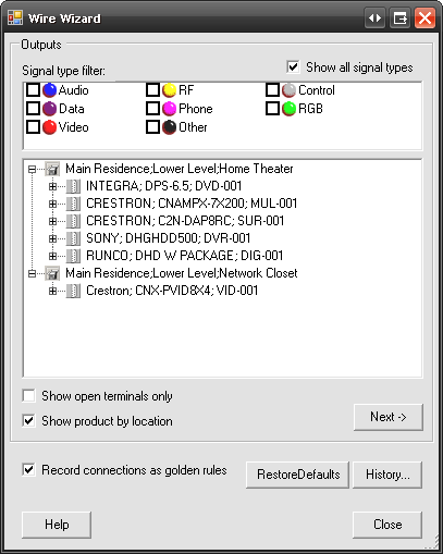
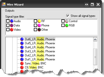
The first screen of the WireWizard form lists all of the Products on the schematic page that have outputs. You may filter by signal type if you wish by checking the boxes in the “Signal type filter” section:
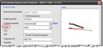
![]() The colored icons next to the signal types reflects the color the wire shape will drop when a wire of that type is dropped on a schematic page. Remember the “Type” field?
The colored icons next to the signal types reflects the color the wire shape will drop when a wire of that type is dropped on a schematic page. Remember the “Type” field?
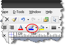
Once the wire shape is on the page, you can use the Visio function “Line Color” to change the color of the shape:
The icons that display next to outputs are colored based on the Signal assigned to the output. These colors are matched to the Signal type based on a text comparison:
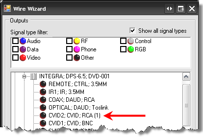
Products display in the format: Manufacuter;Model;Component ID. Click the [+] next to the Products to display the output list. An output that has a wire connected to it on a schematic page will display with a (1) next to it:
There are two additional filters on this form:
Show product by location - groups Products based on their location assignment
Show open terminals only – filters the output list so that outputs that are already connected on the drawing page with a wire shape do not display in the list
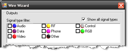
![]() With the exception of the “Show product by location” filter, we do not recommend using the filtering options unless you have verified all Product data as being consistent in naming conventions, e.g. all Audio wire is listed as Type “Audio” and not a mix of “Audio” and “Aud”. This is because our filtering is text based and matches on exact terminology only.
With the exception of the “Show product by location” filter, we do not recommend using the filtering options unless you have verified all Product data as being consistent in naming conventions, e.g. all Audio wire is listed as Type “Audio” and not a mix of “Audio” and “Aud”. This is because our filtering is text based and matches on exact terminology only.
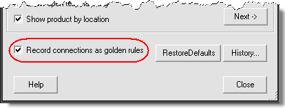
The [RestoreDefaults] button clears any filters that you have selected.
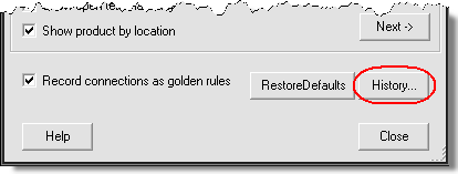
The “Record connections as golden rules” option applies to the AutoWire function discussed below. The [History…] button also applies to the AutoWire function. It allows you to manage the rules you’ve created.
The colored icons that you see next to the outputs for the product are based on the “Type” assigned to the product. The legend is at the top of the form in the “Signal filter type” section.
Click an output to select then click [Next].
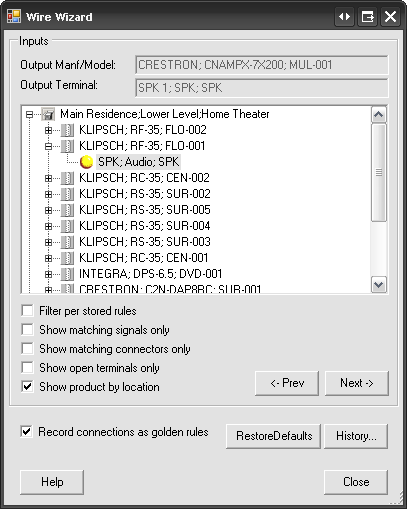
The Product and output terminal that you selected is displayed at the top of the form. The output is displayed in the following format: Label – Signal – Terminal
Click the [+] next to a Product to display the inputs. The icons that display next to inputs are colored based on a text comparison between the output Terminal and Signal, and the input Terminal and signal:
green = both the output and input Terminal and Signal match
yellow = either the output or input Terminal or Signal match
red = neither the output or input Terminal or Signal match
Again, there are many filters here that we do not recommend you use unless you have verified all of your Product data for consistency. Most are self explanatory but just for kicks, here is what each filter does:
| Filter | Description |
| Filter per stored rule | Filters the input list to only those inputs that are associated with a Standard Rule or Golden Rule, i.e. – filters to the inputs that have been connected in the past using Wire Wizard |
| Show matching signals only | Filters the input list to only those inputs where the signal matches the chosen output’s signal |
| Show matching connectors only | Filters the input list to only those inputs where the signal matches the chosen output’s signal |
| Show open terminals only | Filters the input list so that inputs that are already connected on the drawing page with a wire shape do not display in the list |
| Show product by location | Groups Products based on their location assignment |
Select an input and then click [Next].
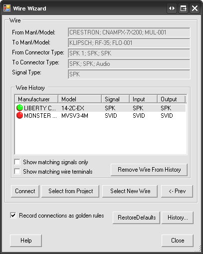
Now the top of the form displays information for both the output and input Products that you have selected. It also lists the signal from the output you chose in the “Signal Type” field.
The Wire History section displays a list of every wire that has been used in the WireWizard. The Manufacturer, Model, Signal, Input, and Output list for each wire. When you make a wire connection using the WireWizard, you are prompted with:
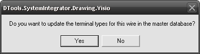
Choosing [Yes] will populate the Signal, Input, and Output fields for the wire in the Wire History. Choosing [No] will not populate the fields:
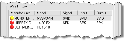
The colored icons next to the wires indicate whether or not the Signal matches the signals from the inputs and outputs you chose:
green = both the output and input signal match the signal assigned to the wire
yellow = either the output or input signal match the signal assigned to the wire
red = neither the output or input signal match the signal assigned to the wire
Use the [Remove Wire From History] button to clean up the list as needed.
The filter choices at this point are:
| Filter | Description |
| Show matching signals only | This will filter the Wire History so that only wires assigned a signal that matches either the output or input signal display, i.e. – only wires with a green or yellow icon will display |
| Show matching wire terminals | This will filter the Wire History so that only wires assigned a terminal that matches both the output or input terminals display, i.e. – only wires with a green icon will display |
You have three options for selecting a wire at this point: [Connect], [Select from Project], and [Select New Wire].
[Connect] – In order to use this button, you must first select a wire listed in the Wire History section of this form. This will add the selected wire to the PDM and automatically drop and connect the wire shape on the page.
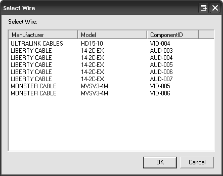
[Select from Project] – This option allows you to use a wire shape that you have already added to the drawing page from your PDM. Using this option will not add a wire to your PDM since you have already used an existing wire from the PDM. A dialog will display showing you all available wire shapes on the drawing page:
[Select New Wire] – This option allows you to select a wire Product from your MasterTable database. You will be prompted to pick a wire from your database. This will add the selected wire to the PDM and automatically drop and connect the wire shape on the page.
When you have made your wire selection, the wire shape will connect on the drawing page and the WireWizard will reset to the first page of the form so you can make your next connection.
Right-Click->D-Tools->Wire Options->AutoWire
This option is only available for use on a schematic page type. The functionality of AutoWire is based of rules that you have “taught” SI 5 through using the WireWizard. Every connection you make using the WireWizard is recorded as a Standard Rule.
![]() The connection is also recorded as a Golden Rule if you have the “Record connections as golden rules” option checked on the WireWizard form.
The connection is also recorded as a Golden Rule if you have the “Record connections as golden rules” option checked on the WireWizard form.
Standard Rules – These rules are based off of the Category and Type fields. This means that if you make a connection between a Product of Category “Video Sources” and Type “DVR” to a Product of type “Display Devices” and Type “Plasma” with a Monster Cable MVSV3-4M cable, the AutoWire function will assume that this same wire is used to connect all Products of Category “Video Sources” and Type “DVR” to Products of type “Display Devices” and Type “Plasma” on the drawing page.
Golden Rules – These rules are based of the Category, Manufacturer, and Model fields. This means that these rules are more specific than Standard Rules and may be your best option for using AutoWire.
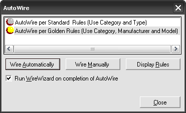
The AutoWire main form looks like this:
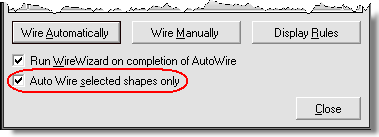
![]() If any shapes are selected on the page prior to running AutoWire, you will see and additional option to just run AutoWire for the selected shapes:
If any shapes are selected on the page prior to running AutoWire, you will see and additional option to just run AutoWire for the selected shapes:
Here you can choose what rules you want use, Standard or Golden, and whether or not you want to [Wire Automatically] or [Wire Manually]. You can also use [Display Rules] to display and manage the rules that have been created:
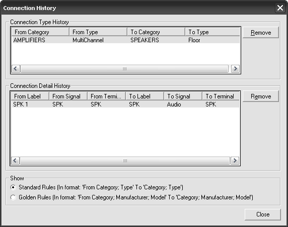
![]() The [Display Rules] button is the same as the [History…] button on the WireWizard form:
The [Display Rules] button is the same as the [History…] button on the WireWizard form:
[Wire Automatically] – This will wire the page based on what type of rules you selected. Always double check the connections after they are made using this feature. Since they are based off of rules that you have created, human error still plays a part here.
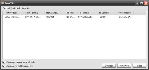
[Wire Manually] – This allows you to choose what connections to make based off of the rules that you have created. This gives you a bit more control over the Wire Automatically function. A form opens allowing you to select rules the rules you wish to apply. Click [Connect] to make the connection or click [New Wire] to select a wire from your database.
- © Copyright 2024 D-Tools