Right Click Menu
Table of contents
- D-Tools/Visio Right-Click Menu Options
- Right-Clicking on Shapes
- Right-Click->Show Text Blocks
- Right-Click->Merge Text Blocks
- Right-Click->Snap Text Block Position
- Right-Click->Show Text Callout
- Right-Click->D-Tools->Find in Project DataMatrix
- Right-Click->D-Tools->Shape->Insert Alternate View
- Right-Click->D-Tools->Shape->Change Shape
- Right-Click->D-Tools->Shape->Generate Side View
- Right-Click->D-Tools->Shape->Link To D-Tools
- Right-Click->D-Tools->Shape->Note
- Right-Click->D-Tools->Terminal Options
- Right-Click->D-Tools->Wire Options->Assign Head End
- Right-Click->D-Tools->Wire Options->Check Connections
- Right-Click->D-Tools->Wire Options->Wire Connection Options
- Right-Click->D-Tools->Wire Options->AutoLayout
D-Tools/Visio Right-Click Menu Options
Your right-click menus will vary depending on whether you right-click a Product in the PDM or if you right-click a shape in the Drawing Area.
When you right click selected Product(s) or Package(s) in the PDM, the right click menu displays as shown below:
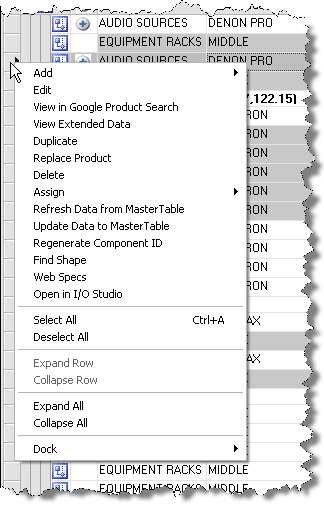
Most of these options were discussed in the Text Project Interface section of this guide. For a complete description see Right-Click Options. The Visio Interface specific options are discussed below.
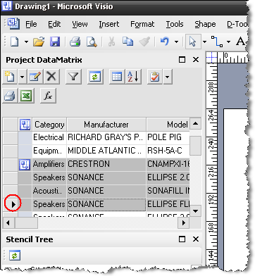
![]() Some of these options will apply across multiple Products, some only for the primary selected Product. A selected Product is indicated by a grey row color, and the primary selected Product is indicated with an arrow in the PDM:
Some of these options will apply across multiple Products, some only for the primary selected Product. A selected Product is indicated by a grey row color, and the primary selected Product is indicated with an arrow in the PDM:
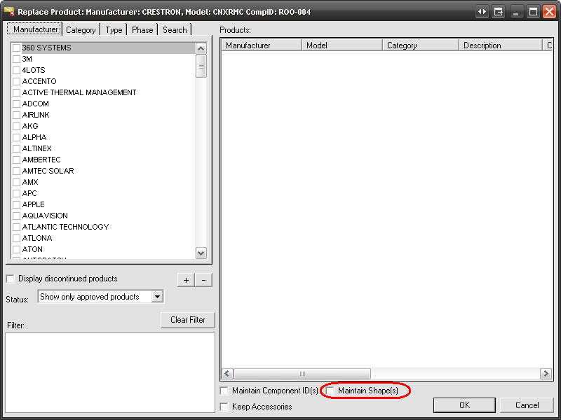
Right-Click->Replace Product
This function is detailed here. In Visio, there is an additional option on the form, "Maintain Shape(s)", allowing you to keep the shapes on the existing pages for replaced products.
Right-Click->Find Shape
This works for the primary selected Product in the PDM. This option will find the shape for that product on the drawing page. The drawing page will zoom out to full screen and the Product shape will be selected on the page.
Right-Click->Dock->Left/Right/Top/Bottom/Float
This option applies to the PDM and will dock or float the window based on your choice.
Right-Clicking on Shapes
When you right click selected Product shapes on a drawing page, the right click menu displays as shown below:
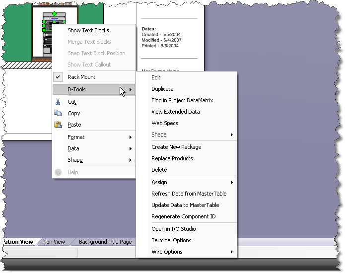
![]() The right-click options will vary depending on what kind of shape you select.
The right-click options will vary depending on what kind of shape you select.
For the following four options, a Line-Image shape is used for the screenshots: Show Text Blocks, Merge Text Blocks, Snap Text Block Position, and Show Text Callout.
Right-Click->Show Text Blocks
Displays the Manufacturer, Model, and Component ID for the Product:
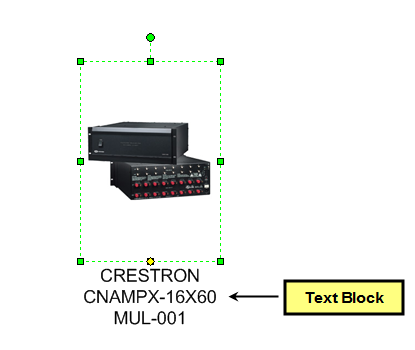
Right-Click->Merge Text Blocks
There are two text blocks, one that displays Manufacturer and Model and one that displays the Component ID. Check this option to keep both of them together or uncheck this option to keep them separated. In the example below, the text blocks are not merged:
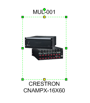
Right-Click->Snap Text Block Position
When this option is checked, the yellow handle for the text block will snap to the handles of the shape. When unchecked, they don’t snap. In both of the screenshots above the text blocks are “snapped” to the shape handles.
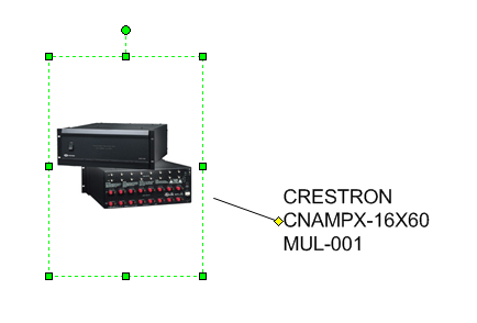
Right-Click->Show Text Callout
This displays a line from the shape to the text block when checked:
Right-Click->D-Tools->Find in Project DataMatrix
This option works for only one selected Shape at a time. This will find and select the Product in the PDM.
Right-Click->D-Tools->Shape->Insert Alternate View
This option allows you to add a second shape to represent the selected Product to the drawing page. The shapes will have the same Component ID as each other. You can choose any shape from any stencil for this second shape.
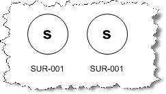
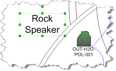
![]() Example: You price your speakers by the pair in your database. When you add the Product to the PDM and then drag the Product to a drawing page, you only get one shape to represent the pair of speakers:
Example: You price your speakers by the pair in your database. When you add the Product to the PDM and then drag the Product to a drawing page, you only get one shape to represent the pair of speakers:
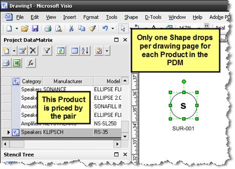
Select the shape and then Right-click->D-Tool->Shape->Insert Alternate View. Select your Stencil and Shape from the form:
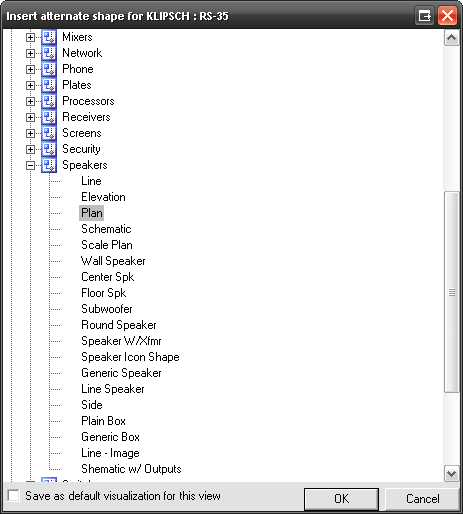
A second shape will display on the drawing page:
Right-Click->D-Tools->Shape->Change Shape
If the default shape that displays on a drawing page is not the shape you want, you can change the shape to any shape from any stencil.
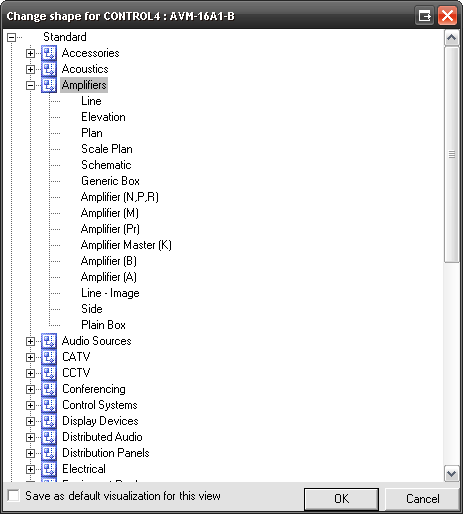
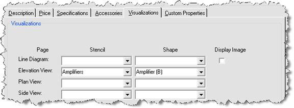
The “Save as default…” checkbox will save this setting for future use. The setting is displayed on the Visualization tab of the Product Properties form. You can also manually set these directly on the Visualizations tab.
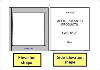
Right-Click->D-Tools->Shape->Generate Side View
This option will only work on an elevation page type. This will add a very basic side view of the selected Product. The side view shape is to scale based on the Height and Depth of the Product.
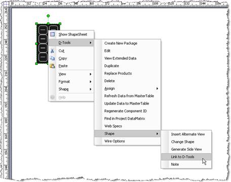
Right-Click->D-Tools->Shape->Link To D-Tools
This option allows you to link a shape that you have created to a Product in the SI 5 database. Once you create a shape and link it to a Product in SI 5, you may want to add the shape you created to a stencil so that you can use it in future Projects.
![]() Example: In this example, I created a very simple 8-button plate shape using standard Visio drawing tools that I want to link to a Product in my SI 5 database.
Example: In this example, I created a very simple 8-button plate shape using standard Visio drawing tools that I want to link to a Product in my SI 5 database.
1) Select the shape you want to link then Right-Click->D-Tools-> Shape->Link To D-Tools:
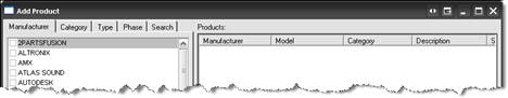
2) Select the Product that you want to link this shape to on the Add Product form:
3) The shape is now linked to the Product that you selected and the Product has been added to the PDM.
4) To add this shape to a stencil for use on future Projects:
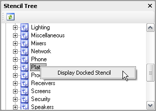
5) Right-click the stencil and select “Display Docked Stencil”. In this example, I chose the Plates stencil:
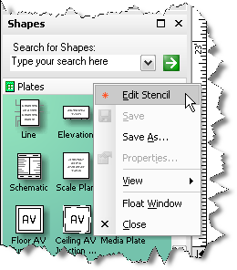
6) Once the stencil is docked, right-click where the stencil name is displayed in the Shapes window and select Edit Stencil:
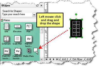
7) Now drag the shape from the drawing page into the docked stencil:
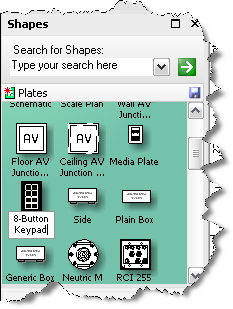
8) The shape will now display inside of the stencil. Rename the shape to an appropriate name.
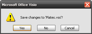
9) Right-click the stencil name and select “Edit Stencil” to take the stencil out of edit mode. Save changes to the stencil.
10)Now anytime that you drag this shape over to a drawing page, you will be prompted to select the Product you assigned to this shape.
![]() This function is a one-to-one relationship with a Product in the SI 5 database as opposed to a one-to-many relationship like the standard SI 5 shapes.
This function is a one-to-one relationship with a Product in the SI 5 database as opposed to a one-to-many relationship like the standard SI 5 shapes.
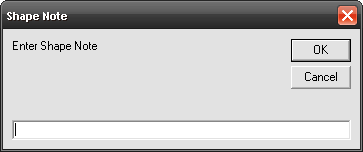
Right-Click->D-Tools->Shape->Note
This option lets you add a note about a particular shape on a drawing page. The note will appear as a text box on the drawing page and can be moved/edited on the drawing page.
Right-Click->D-Tools->Terminal Options
This option is only available for use on a schematic page type. This form allows you to pick and choose what signal points display on the shapes on the drawing page.
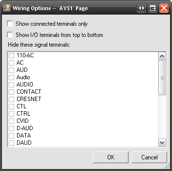
You can choose to “Show connected terminals only” when you are finished with a drawing page. This will “collapse” the schematic shapes on the page by hiding unused inputs and outputs. The “Show I/O terminals from top to bottom” will invert the I/Os on the shape.
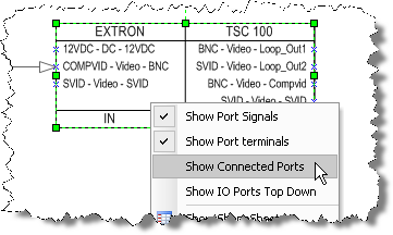
![]() Instead of using the “Display connected ports only” and “Show I/O ports from top to bottom” options globally for the schematic page, you can right-click specific schematic shapes on the drawing page and select “Display Connected Ports” and/or “Show IO Ports Top Down”:
Instead of using the “Display connected ports only” and “Show I/O ports from top to bottom” options globally for the schematic page, you can right-click specific schematic shapes on the drawing page and select “Display Connected Ports” and/or “Show IO Ports Top Down”:
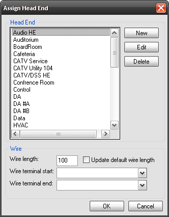
Right-Click->D-Tools->Wire Options->Assign Head End
The Head End assignment only applies to Wire and Cable, and only to Wire and Cable assigned to a Phase that has the associated Head End action. Confused? Head End is the “end point” of the wire. By default, the “Rough-In” phase is the only SI 5 phase that ships with the Head End action. When a “Rough-In” Wire is added to a Project, the Head End dialog box opens as shown below:
If you ever want to reassign a Head End once the Product is added to the PDM, use this right-click option.
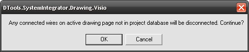
Right-Click->D-Tools->Wire Options->Check Connections
This function is a part of the wire auditing in SI 5. If you have turned off the “Prompt on Conflict” setting on your Wire Connection Options (see below) you would use this function to verify that you have no conflicting wire connections.
Right-Click->D-Tools->Wire Options->Wire Connection Options
This function gives you flexibility on how wire connections behave and whether or not they are recorded for reporting purposes. These settings let you choose how the wire auditing in SI 5 functions.
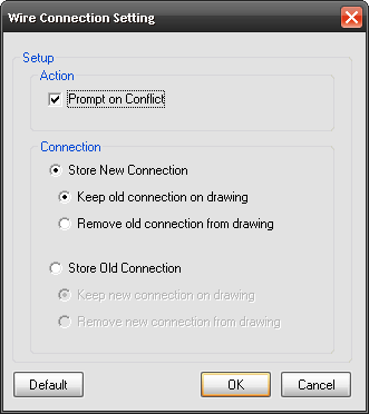
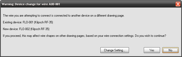
Prompt on Conflict –When this option is checked you will see a similar prompt to the one below letting you know that there is a conflict. The [Change Setting…] button will open the Wire Connection Setting shown above. Even if you do not have this box checked, your settings in the “Connection” section of the form still apply.
Connection Settings – there are two main options here: Store New Connection or Store Old Connection. Only one connection can be “stored” for each end of a wire. This “stored” connection is what gets passed to our reporting engine. The two sub-options for each of the main options deals with how you want the old or new connection to display on the drawing. You can either leave it connected by using the “Keep old/new connection on drawing” option or you can have the shapes separate by using the “Remove old/new connection from drawing” option. This is aesthetic only since only one connection can be “stored” as stated above.
Right-Click->D-Tools->Wire Options->AutoLayout
This option is only available for use on a schematic page type. This function will move shapes of a particular Category to the quadrant of the drawing page based on your selections.
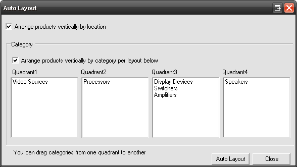
To use, drag a Category to the desired quadrant column and then click [Auto Layout]. All of the shapes on the drawing page will move over and group in the selected quadrant. Only the Categories in the project will display.
Arrange products vertically by location – arranges the Products based on their location assignment and the location hierarchy you have established for the Project
Arrange products vertically by category per layout below – arranges the Products vertically based on their position from top to bottom in each quadrant
- © Copyright 2024 D-Tools