Plan
Visio Plan View
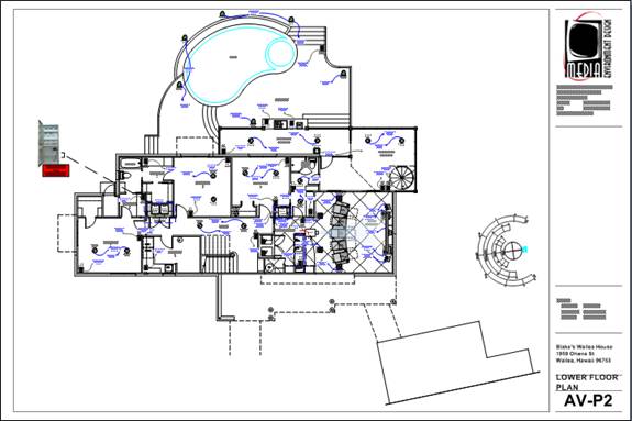
The plan page type is generally used with a floor plan to show an overhead view of where products are installed in a Project. An example of a Plan drawing page is below:
The shapes that are intended for use on a plan drawing page type are very basic shapes. There are two different style shapes you can use on this page type: Plan shapes and Scale Plan shapes. If you want to change the default shape that drops, see the Right-Click Options.
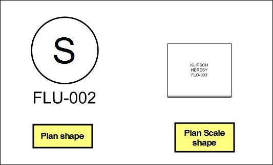
Plan shapes are not to scale and can be resized. Most stencils also have a Scale Plan shape that is to scale based on the Products width and depth. Scale Plan shapes cannot be resized using the selection handles. In order to resize them, you must make changes to the properties of the Product.
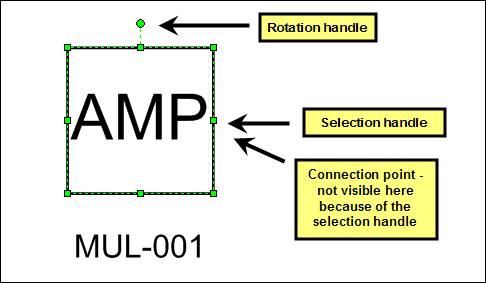
The connection points on these shapes are intended for use with Wire and Cable shapes. The connections made with Wire and Cable shapes are recorded for reporting. Example reports are the Brother Wire Labels and the Wire Checklist reports. See Brother Wire Labels or more detail.
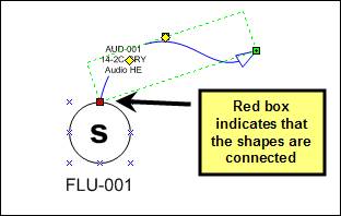
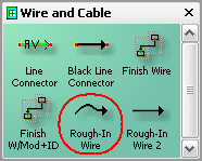
The wire and cables shape that drops by default on a plan page is the Rough-In Wire shape:
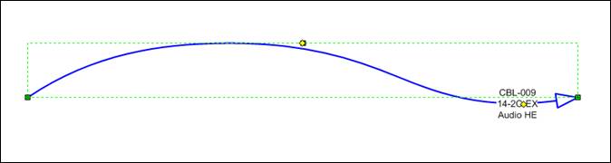
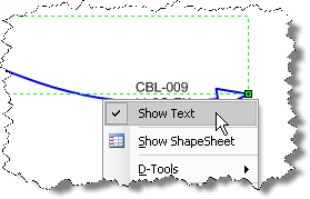
There is a connection point at each end of the wire and the text block displays the Component ID, Model, and Head End. Right-clicking allows you to hide the text block:
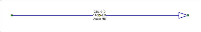
The Rough-In Wire 2 shape is straight, not squiggly:
To change a shape, see the Right-Click Menu options.
If a wire shape is connected to another shape on a Visio page, if you drag that product to another page the wire will automatically on the page as well.
Inserting an AutoCAD File
Inserting a file of the floor plan is ideal because it saves you the trouble of drawing out rooms. Ideally you would insert an AutoCAD file onto the Visio page or you can insert an image of the floor plan if that is all you have. You can insert AutoCAD files directly on the page or you could insert them on background pages if you wish.
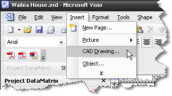
![]() Inserting a CAD drawing saves a ton of time and it is a function of Visio:
Inserting a CAD drawing saves a ton of time and it is a function of Visio:
The form will default to Custom scale because Visio makes an attempt to fit the CAD drawing on the page.
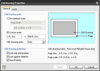
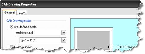
You can leave it if you are not worried about scale or you can select Pre-defined scale, select Architectural, and then select 1/4” = 1’ (if you know what scale the CAD drawing is, use that instead). Click [Apply] to see if this size works. If it does not, then you can change your Visio drawing page scale and try inserting the CAD drawing again.
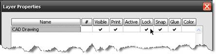
Once the AutoCAD drawing is on the page, you will want to lock it so you don’t accidentally select the CAD image. To do this, right-click anywhere on the drawing page and select View->Layer Properties… Click the cell in the “Lock” column.
Preparing an AutoCAD file for Visio
The AutoCAD file must be “cleaned” before it can be inserted into Visio. This cleaning must be done in AutoCAD or an AutoCAD-ish program. If you do not have a copy of AutoCAD, you may want to check out this free software that will allow you to modify your CAD file. Or you may want to ask the architect or builder to do this for you. Click here to download a PDF file of the instructions below.
The most common error you will see when importing an AutoCAD file into Visio is this:
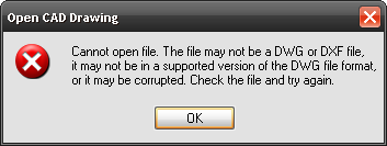
The most common reason for this error is that the AutoCAD file is not in AutoCAD 2000 (or earlier) format. The method described below will take care of this error as well as other issues that are encountered when inserting an AutoCAD file into Visio.
1) Verify that the Drawing (.DWG) is in Model Space (not Paper Space).
2) Run the Command: zoom extents
3) Verify that there is only one “image” in the Drawing. Many AutoCAD Drawings have multiple “images” as shown below:
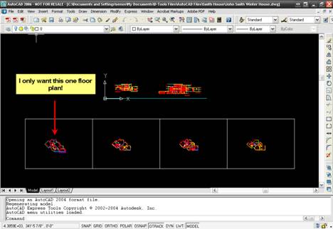
To create a new separate drawing file for each view that you want, follow these steps:
a) Run the command wblock. The Write Block form will open:
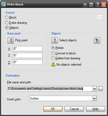
b) Click the [Select objects] button ![]() .
.
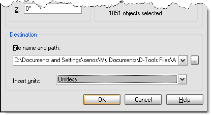
c) Select the objects that you want and then click [Enter] on the keyboard. You will be returned to the Write Block form. Choose a file name and path, and change the Insert units to “Unitless”.
d) Now you would open the new file you just created in AutoCAD and start over with the “Preparing an AutoCAD file for insertion into Visio” process.
4) Run the Command: units The Drawing Units dialog will open. Verify that the “Type” is set to Architectural and the “Units to scale inserted content” is set to Unitless.
5) Run the Command: xref The Xref Manager dialog will open. If there are xrefs, you can Bind them or if the Status of the xrefs is “Not Found” or “Unloaded”, Detach them.
6) Run the Command: purge The Purge dialog will open. Check “Purge nested items” and uncheck “Confirm each item to be purged”
7) Run the Command: audit
8) Type “y” to fix any errors.
9) Save the drawing as an R14 DWG or an R12 DXF file if these are options in your version of AutoCAD. If you don’t have one of these options you can save as an AutoCAD 2000 DWG.
The procedure described above will work for most AutoCAD Drawings. For instructions on importing an AutoCAD Drawing into Visio, adding Visio Shapes, then exporting back to AutoCAD (“Round Tripping”) see Round Tripping: AutoCAD to Visio…then back to AutoCAD.
- © Copyright 2024 D-Tools