Home > SI5 Documentation > User Guide > Visio Interface > NEW Beta Wire Shape
NEW Beta Wire Shape
NEW Beta Wire Shape
Table of contents
Beta Finish Wire Shape
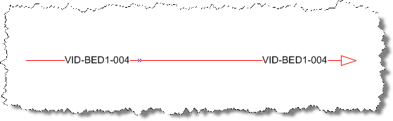
We are pleased to offer a Beta release of a new Visio wire shape for you to use on schematic drawings. This new shape displays the ComponentID on both ends of the wire by default.
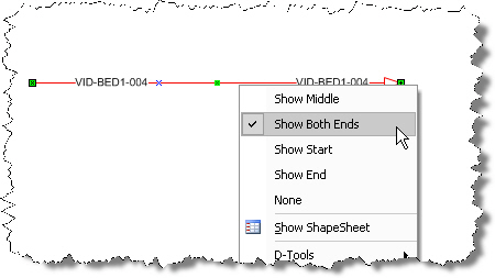
When you right-click the shape, you have the option of choosing the location of the ComponentID:
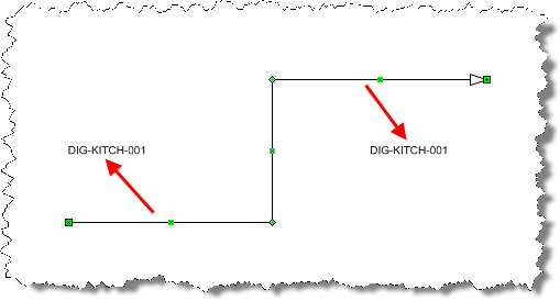
When the shape is first placed on a drawing sheet, the labels are not “glued” to the shape so if you move the wire, the labels will not remain on the shape:
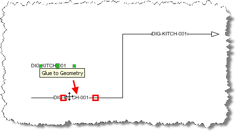
The easy fix for this is to select the ComponentID text label (it will have green handles when selected) and then drag over to the wire shape. You will see red “glue to” boxes appear:
To try out the shape:
- Download the stencil from here. This is a zip file named “Wire and Cable – New Beta Finish Wire Double ComponentID.zip”.
- Unzip the file to the following location:
XP - C:\Documents and Settings\All Users\Application Data\D-Tools\SI5\Visualizations\Stencils
Vista/Win7 – C:\ProgramData\D-Tools\SI5\Visualizations\Stencils
- Open a Visio project file and you will see the stencil listed under our Custom section of your Stencil Tree.
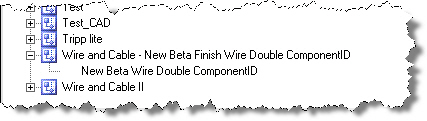
- Drag the “New Beta Wire Double ComponentID” shape to a schematic page and select a product from your database.
6-23-2010 - Updated the stencil to one that does not throw the "Enable Macros" prompt
We welcome your feedback.
Also see:
- © Copyright 2024 D-Tools