Home > SI 2017 Documentation > Knowledge Base > Creating Custom Blocks
Creating Custom Blocks
Creating Custom Blocks
![]()
Overview
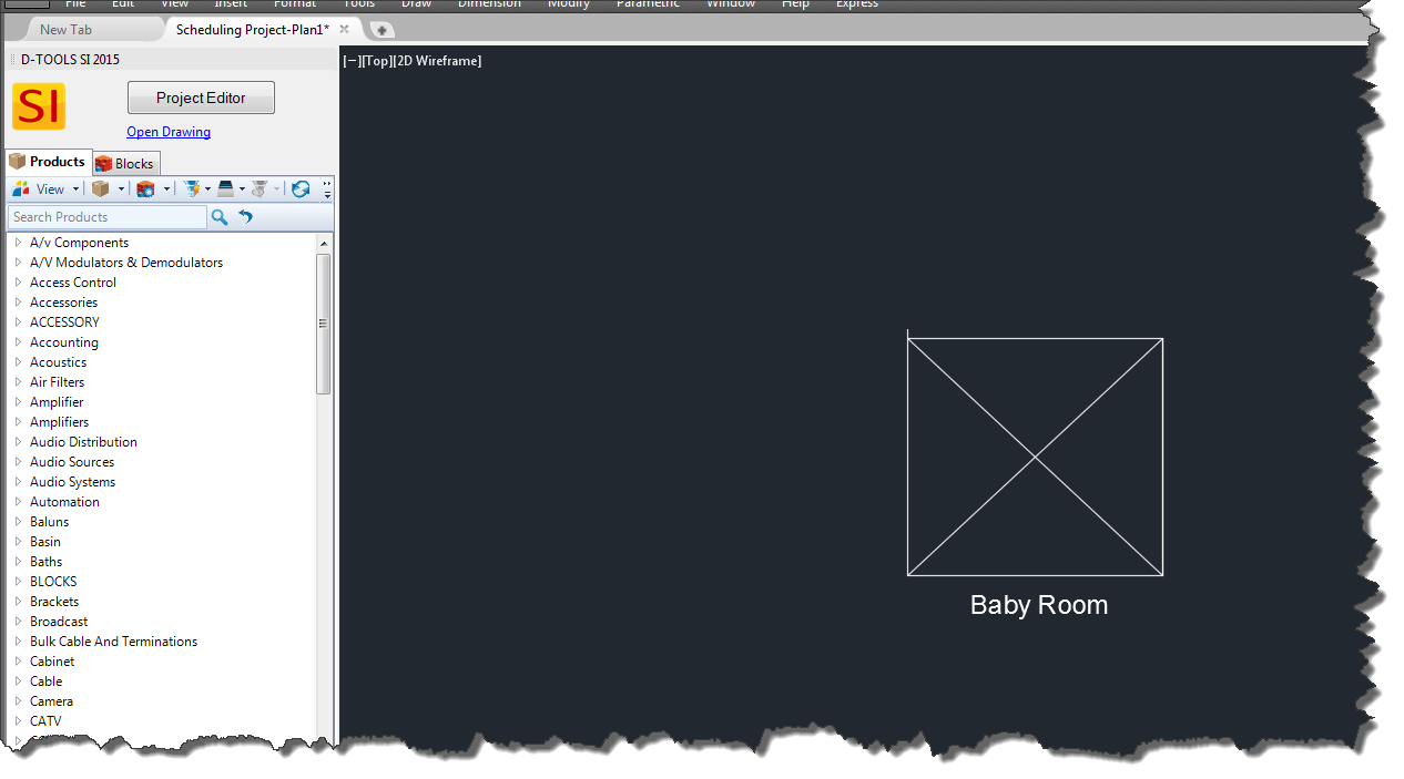
Custom blocks can be created within AutoCAD and imported into the AutoCAD Drawing Add-In. This article will cover the steps needed to create the block as well as how to make the block available to use when using the SI 2017 and AutoCAD integration.
Steps
- Open AutoCAD outside of our program.
- Create a new .dwg file.
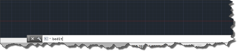
- Once the new drawing file is opened, type “bedit” to open the block editor.
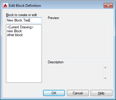
- Within the Edit Block Definition pop-up, type in the desired name of the block and click OK.\
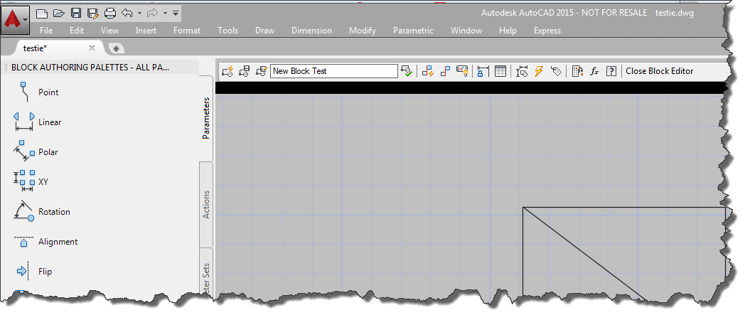
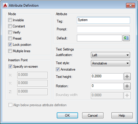
- Draw the Desired block. Once you have drawn the block to your liking, click on the “Define Attribute” icon to input the desired attribute such as location or system.
List of Available Attributes
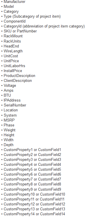
- Input the desired Attribute into the Tag section and place the Tag in the desired location. All Blocks must have am attribute defined to be displayed on the Drawing Add In.
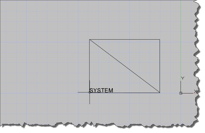
- Once all the changes have been made to the Block click on the “Save Block Definition” icon and close the Block Editor by clicking the “Close Block Editor” button. Multiple Blocks can be done within one drawing, but each block must have a defined attribute.

- Save the Drawing and close the drawing.
- Open an AutoCAD drawing via our software.
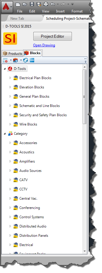
- On the AutoCAD Add In, click on the Block tab and select Manage Blocks button and click Add Block Files.
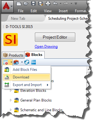
- Browse for the drawing and click OK. The block will now be able for you to insert into your drawings.
- © Copyright 2024 D-Tools